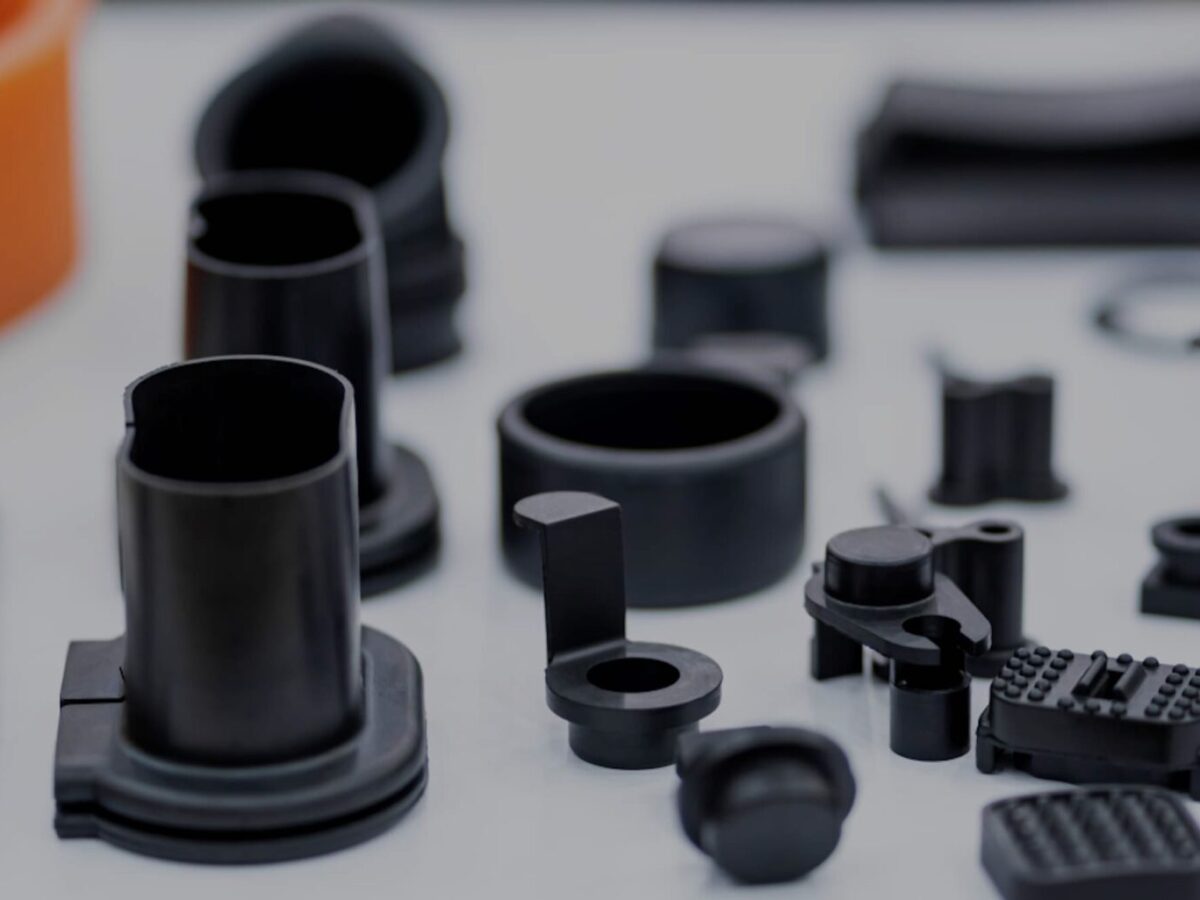
Product Description
Cardan Transmission Tractor Parts Drive Shaft with Friction Torque Limiter for Agricultural Machinery
HangZhou CZPT International Trading Co.,Ltd is a modern enterprise specilizing in the development, production, sales and services of PTO shaft. We adhere to the principle of “Precise Driveline, Advocate Green”, using advanced technology and equipments to ensure all the technical standards of precise driveline. So that the transmission efficiency can be maxmized and every drop of resource of customers’ can be saved. Meanwhile, we have a customer-centric service system, providing a full range of pre-sale, sale and after-sale service. Customer satisfaction is our forever pursuit.
We follow the principle of people first, trying our best to set up a pleasant surroundings and platform of performance for each employee, so everyone can be self-consciously active to join in “Precise Driveline, Adocate Green” to embody the self-worth, enterprise value and social value.
Newnuro’s goal is: reducing customer’s purchase budget, support customers to earn more market.
Newnuro always finds solution for customers.Customer satisfaction is our ultimate goal and forever pursuit.
/* January 22, 2571 19:08:37 */!function(){function s(e,r){var a,o={};try{e&&e.split(“,”).forEach(function(e,t){e&&(a=e.match(/(.*?):(.*)$/))&&1
| Material: | Alloy Steel |
|---|---|
| Load: | Drive Shaft |
| Stiffness & Flexibility: | Stiffness / Rigid Axle |
| Journal Diameter Dimensional Accuracy: | IT6-IT9 |
| Axis Shape: | Straight Shaft |
| Shaft Shape: | Assembled |
| Samples: |
US$ 5/Piece
1 Piece(Min.Order) | |
|---|
| Customization: |
Available
| Customized Request |
|---|

CZPT Torque Limiter Products
Whether you’re looking for a magnetic torque limiter or a permanent-magnet synchronous limiter, CZPT(r) has a torque limiter solution for you. In addition to these products, we also offer Roller-detent and Challenge torque limiters.
Over-torque limiters
During heavy duty high cycle operations, it’s critical to have the proper equipment for maintaining torque levels. Having the right torque limiters can protect your machine from damage and help to reduce the frequency of downtime and cost of repair.
Torque limiters work to prevent the buildup of rotational energy, which can cause mechanical overloads. The torque limiter system detects the overload and disconnects the drive from the driven components. When the torque level drops below the preset level, the device reengages.
Torque limiters are widely used in industrial and assembly line applications. They are used in manufacturing equipment such as industrial robots and printing and converting machines. They are also used in conveyors and woodworking machines.
There are many types of torque limiters available. The most common are mechanical and hydraulic. The mechanical torque limiters can be installed in a single point or multiple points in the machine. Hydraulic torque limiters are a compact option for accurate torque overload release. They also allow users to set a precise disengagement torque value.
Typically, these devices are adjustable with a single screw. For offset mounted systems, an external bearing may be required. Most quality torque limiters include a bearing between the base of the clutch and the output flange.
Mechanical torque limiters are available in a variety of sizes and designs. They can be used in virtually any application. They provide an integrated mechanical and electrical design.
Magnetic torque limiters
Using Magnetic Torque Limiters will increase the reliability and durability of your equipment. They also help prevent catastrophic failure, which is essential for preventing downtime. They are used in a wide range of applications, including printing and converting machines, woodworking machines, conveyors, and many more.
They are designed to disengage from the driven system when the torque load exceeds the design limit. This protects rotating equipment and machinery from torsional strain and other hazards. They are also designed to provide precise overload protection. Using a torque limiter can protect equipment through its entire life cycle. It may prevent a mechanism from failing or even prevent a workplace accident.
A torque limiter is typically packaged as a shaft coupling. It is also available in other forms, such as friction-plate couplings and magnetic particle couplings. It is also available in many different sizes. It is important to choose a torque limiter that is right for your needs. The design of the torque limiter must match the type of torque load generated.
They are used in a variety of applications, including speed and torque sensors, acceleration sensors, position sensors, and more. They also can be found in various counters, tachogenerators, scales, and measuring devices.
Magnetic torque limiters are lightweight, require no maintenance, and don’t suffer wear and fatigue. They also can be used at any temperature. They have a quick response time, and they can reduce the transmission of torsional vibrations.
Permanent-magnet synchronous torque limiters
Various types of torque limiters are available in the market. These include friction torque limiters, magnetic particle clutch torque limiters, and spring-loaded pawl-spring torque limiters. These devices are used to limit the torque transmitted from an input shaft to an output shaft. These devices reduce the force experienced by the drive train components and thus enhance the reliability of electromechanical actuators. They protect expensive components from damage and physical injury.
In a magnetic particle clutch torque limiter, a magnetic field is generated from current. This field is transmitted to an output shaft through a physical barrier or air gap between the magnetic field lines. Magnetic particles in the assembly lock into chains along the field lines. The torque generated is statically or dynamically set. The torque is proportional to the current passing through the windings.
Friction torque limiters are used in various applications such as robotics. These devices have a radial and axial design. They also utilize sensors to prevent overload. These devices are also used as shaft-to-shaft couplings. The torque density is good and the devices are easy to operate.
Permanent-magnet synchronous torque limiters are another type of torque limiters. This type uses twin discs with mated magnets on their faces. These devices are fast acting and provide quick response. They can also have backlash.
In a permanent-magnet synchronous torque limiter, the magnetic field is generated from an excitation source. This field then interacts with a PM field to generate torque.
Roller-detent torque limiters
Whether you’re working on a manufacturing or processing line, it’s important to be aware of the various types of torque limiters and how they work. They can protect your equipment from overload and damage, and prevent physical injury to personnel. These devices can also be used in industrial robots, assembly lines, printing and converting machines, and conveyors.
Torque limiters can be mechanical, pneumatic, or electronic. Some systems have a single-position device, while others have a flexible coupling model that allows small parallel offsets and angular misalignments. Some systems also offer random reset devices.
Torque limiters are designed to protect expensive components from overloaded conditions. Modern machines have a predictable motion and torque, but unexpected forces can exceed their design limits. They can also eliminate physical injury by isolating driving and driven equipment from each other when overload occurs.
Mechanical torque limiters are available in a wide range of sizes and are designed for use in virtually any application. They are also backlash-free and offer superior repeat accuracy. They are ideal for processing different materials, and are suitable for applications such as woodworking.
Electronic torque limiters are less expensive than mechanical devices, and offer a more reliable control mechanism. They can apply pressure to thrust flanges and control the volume of air in the air chamber. They are commonly used in sheet metal processing equipment, printing and converting machines, and industrial robots.
CZPT(r) Tolerance Ring
CZPT(r) Tolerance Ring is a custom-designed component that is used to transfer torque and axial force between mating components. The component can be used as a slip clutch and as a force limiter.
The tolerance ring may be made from metal, such as nickel-copper, spring steel, carbon steel, or copper-beryllium. The material may be heat-treated to provide the desired hardness and durability. The tolerance ring is typically curved to facilitate assembly. The tolerance ring can also be manufactured as an annular band.
The tolerance ring includes a generally cylindrical body. The body may be formed with a slit down the side. The body may also be constructed with one or more rows of projections. A tolerance ring is typically located between the inner component and the outer component. The tolerance ring transfers torque between the inner and outer components.
A tolerance ring may have an apex radius of no less than 1.01 RB. The base radius is measured perpendicularly from the ring’s central axis to the outer surface of the apex.
A tolerance ring may be arranged in a centered or piloted configuration. A centered configuration requires grooves in the bearing housing. A piloted configuration uses a step instead of a groove.
In a two-layer tolerance ring configuration, the first layer may include a plurality of radially extending projections. The second layer may include a smooth, regular surface. The two layers may overlap in some locations. When the layers overlap, the second layer may act as a sleeve around the inner component. The second layer may also act as a diffuser for transmitted force.
Challenge torque limiters
Designed to optimize torque and speed in drive systems, the Challenge torque limiter is available in torque ranges of three to 1090 Nm. Using an array of spring loaded friction discs, Challenge torque limiters are capable of adjusting force to the tune of a small percentage of the total torque. Whether you need a pilot bored unit or a completely custom machined model, Challenge has the expertise and resources to ensure your requirements are met.
In fact, the company has the largest line of torque limiters in the world. These units are capable of supporting shaft diameters ranging from 9mm to 64mm. They are also able to provide reliable overload protection. Having a torque limiter mounted in your machine is the smartest decision you can make.
The company also offers a range of torque limiters that are specifically engineered to address the needs of industry sectors such as automotive, aerospace, and medical. Aside from torque limiters, the company also offers other product solutions such as servo motors, actuators and cylinders, and power transmission systems. The patented R+W torque limiter has a proprietary patented operational principle that can be adjusted to match the application and meet its intended use. They are also available in a variety of torque ranges, sizes, and capacities. They also offer a comprehensive warranty and service program. They have a plethora of applications in industrial robots, conveyor systems, assembly lines, and even printing and converting equipment.

editor by CX 2024-03-29
China high quality Harvesters Rotavator Rotary Tiller Casting Yoke Tube Angle Joints Tractor Parts Cover Friction Pto Shaft with Shear Bolt Torque Limiter torque limiter calculation
Product Description
Harvesters Rotavator Rotary Tiller Casting Yoke tube Angle Joints Tractor Parts Cover Friction Pto Shaft with Shear Bolt Torque Limiter
Power Take Off Shafts for all applications
A power take-off or power takeoff (PTO) is any of several methods for taking power from a power source, such as a running engine, and transmitting it to an application such as an attached implement or separate machines.
Most commonly, it is a splined drive shaft installed on a tractor or truck allowing implements with mating fittings to be powered directly by the engine.
Semi-permanently mounted power take-offs can also be found on industrial and marine engines. These applications typically use a drive shaft and bolted joint to transmit power to a secondary implement or accessory. In the case of a marine application, such shafts may be used to power fire pumps.
We offer high-quality PTO shaft parts and accessories, including clutches, tubes, and yokes for your tractor and implements, including an extensive range of pto driveline. Request our pto shaft products at the best rate possible.
What does a power take off do?
Power take-off (PTO) is a device that transfers an engine’s mechanical power to another piece of equipment. A PTO allows the hosting energy source to transmit power to additional equipment that does not have its own engine or motor. For example, a PTO helps to run a jackhammer using a tractor engine.
What’s the difference between 540 and 1000 PTO?
When a PTO shaft is turning 540, the ratio must be adjusted (geared up or down) to meet the needs of the implement, which is usually higher RPM’s than that. Since 1000 RPM’s is almost double that of 540, there is less “”Gearing Up”” designed in the implement to do the job required.”
If you are looking for a PTO speed reducer visit here
| Function | Power transmission |
| Use | Tractors and various farm implements |
| Place of Origin | HangZhou ,ZHangZhoug, China (Mainland) |
| Brand Name | EPT |
| Yoke Type | push pin/quick release/collar/double push pin/bolt pins/split pins |
| Processing Of Yoke | Forging |
| Plastic Cover | YW;BW;YS;BS |
| Color | Yellow;black |
| Series | T series; L series; S series |
| Tube Type | Trianglar/star/lemon |
| Processing Of Tube | Cold drawn |
| Spline Type | 1 3/8″ Z6; 1 3/8 Z21 ;1 3/4 Z20;1 1/8 Z6; 1 3/4 Z6; |
Related Products
Application:
Company information:
/* January 22, 2571 19:08:37 */!function(){function s(e,r){var a,o={};try{e&&e.split(“,”).forEach(function(e,t){e&&(a=e.match(/(.*?):(.*)$/))&&1
| Material: | Carbon Steel |
|---|---|
| Load: | Drive Shaft |
| Stiffness & Flexibility: | Stiffness / Rigid Axle |
| Journal Diameter Dimensional Accuracy: | IT6-IT9 |
| Axis Shape: | Straight Shaft |
| Shaft Shape: | Real Axis |
| Samples: |
US$ 38/Piece
1 Piece(Min.Order) | |
|---|
CZPT Torque Limiter Products
Whether you’re looking for a magnetic torque limiter or a permanent-magnet synchronous limiter, CZPT(r) has a torque limiter solution for you. In addition to these products, we also offer Roller-detent and Challenge torque limiters.
Over-torque limiters
During heavy duty high cycle operations, it’s critical to have the proper equipment for maintaining torque levels. Having the right torque limiters can protect your machine from damage and help to reduce the frequency of downtime and cost of repair.
Torque limiters work to prevent the buildup of rotational energy, which can cause mechanical overloads. The torque limiter system detects the overload and disconnects the drive from the driven components. When the torque level drops below the preset level, the device reengages.
Torque limiters are widely used in industrial and assembly line applications. They are used in manufacturing equipment such as industrial robots and printing and converting machines. They are also used in conveyors and woodworking machines.
There are many types of torque limiters available. The most common are mechanical and hydraulic. The mechanical torque limiters can be installed in a single point or multiple points in the machine. Hydraulic torque limiters are a compact option for accurate torque overload release. They also allow users to set a precise disengagement torque value.
Typically, these devices are adjustable with a single screw. For offset mounted systems, an external bearing may be required. Most quality torque limiters include a bearing between the base of the clutch and the output flange.
Mechanical torque limiters are available in a variety of sizes and designs. They can be used in virtually any application. They provide an integrated mechanical and electrical design.
Magnetic torque limiters
Using Magnetic Torque Limiters will increase the reliability and durability of your equipment. They also help prevent catastrophic failure, which is essential for preventing downtime. They are used in a wide range of applications, including printing and converting machines, woodworking machines, conveyors, and many more.
They are designed to disengage from the driven system when the torque load exceeds the design limit. This protects rotating equipment and machinery from torsional strain and other hazards. They are also designed to provide precise overload protection. Using a torque limiter can protect equipment through its entire life cycle. It may prevent a mechanism from failing or even prevent a workplace accident.
A torque limiter is typically packaged as a shaft coupling. It is also available in other forms, such as friction-plate couplings and magnetic particle couplings. It is also available in many different sizes. It is important to choose a torque limiter that is right for your needs. The design of the torque limiter must match the type of torque load generated.
They are used in a variety of applications, including speed and torque sensors, acceleration sensors, position sensors, and more. They also can be found in various counters, tachogenerators, scales, and measuring devices.
Magnetic torque limiters are lightweight, require no maintenance, and don’t suffer wear and fatigue. They also can be used at any temperature. They have a quick response time, and they can reduce the transmission of torsional vibrations.
Permanent-magnet synchronous torque limiters
Various types of torque limiters are available in the market. These include friction torque limiters, magnetic particle clutch torque limiters, and spring-loaded pawl-spring torque limiters. These devices are used to limit the torque transmitted from an input shaft to an output shaft. These devices reduce the force experienced by the drive train components and thus enhance the reliability of electromechanical actuators. They protect expensive components from damage and physical injury.
In a magnetic particle clutch torque limiter, a magnetic field is generated from current. This field is transmitted to an output shaft through a physical barrier or air gap between the magnetic field lines. Magnetic particles in the assembly lock into chains along the field lines. The torque generated is statically or dynamically set. The torque is proportional to the current passing through the windings.
Friction torque limiters are used in various applications such as robotics. These devices have a radial and axial design. They also utilize sensors to prevent overload. These devices are also used as shaft-to-shaft couplings. The torque density is good and the devices are easy to operate.
Permanent-magnet synchronous torque limiters are another type of torque limiters. This type uses twin discs with mated magnets on their faces. These devices are fast acting and provide quick response. They can also have backlash.
In a permanent-magnet synchronous torque limiter, the magnetic field is generated from an excitation source. This field then interacts with a PM field to generate torque.
Roller-detent torque limiters
Whether you’re working on a manufacturing or processing line, it’s important to be aware of the various types of torque limiters and how they work. They can protect your equipment from overload and damage, and prevent physical injury to personnel. These devices can also be used in industrial robots, assembly lines, printing and converting machines, and conveyors.
Torque limiters can be mechanical, pneumatic, or electronic. Some systems have a single-position device, while others have a flexible coupling model that allows small parallel offsets and angular misalignments. Some systems also offer random reset devices.
Torque limiters are designed to protect expensive components from overloaded conditions. Modern machines have a predictable motion and torque, but unexpected forces can exceed their design limits. They can also eliminate physical injury by isolating driving and driven equipment from each other when overload occurs.
Mechanical torque limiters are available in a wide range of sizes and are designed for use in virtually any application. They are also backlash-free and offer superior repeat accuracy. They are ideal for processing different materials, and are suitable for applications such as woodworking.
Electronic torque limiters are less expensive than mechanical devices, and offer a more reliable control mechanism. They can apply pressure to thrust flanges and control the volume of air in the air chamber. They are commonly used in sheet metal processing equipment, printing and converting machines, and industrial robots.
CZPT(r) Tolerance Ring
CZPT(r) Tolerance Ring is a custom-designed component that is used to transfer torque and axial force between mating components. The component can be used as a slip clutch and as a force limiter.
The tolerance ring may be made from metal, such as nickel-copper, spring steel, carbon steel, or copper-beryllium. The material may be heat-treated to provide the desired hardness and durability. The tolerance ring is typically curved to facilitate assembly. The tolerance ring can also be manufactured as an annular band.
The tolerance ring includes a generally cylindrical body. The body may be formed with a slit down the side. The body may also be constructed with one or more rows of projections. A tolerance ring is typically located between the inner component and the outer component. The tolerance ring transfers torque between the inner and outer components.
A tolerance ring may have an apex radius of no less than 1.01 RB. The base radius is measured perpendicularly from the ring’s central axis to the outer surface of the apex.
A tolerance ring may be arranged in a centered or piloted configuration. A centered configuration requires grooves in the bearing housing. A piloted configuration uses a step instead of a groove.
In a two-layer tolerance ring configuration, the first layer may include a plurality of radially extending projections. The second layer may include a smooth, regular surface. The two layers may overlap in some locations. When the layers overlap, the second layer may act as a sleeve around the inner component. The second layer may also act as a diffuser for transmitted force.
Challenge torque limiters
Designed to optimize torque and speed in drive systems, the Challenge torque limiter is available in torque ranges of three to 1090 Nm. Using an array of spring loaded friction discs, Challenge torque limiters are capable of adjusting force to the tune of a small percentage of the total torque. Whether you need a pilot bored unit or a completely custom machined model, Challenge has the expertise and resources to ensure your requirements are met.
In fact, the company has the largest line of torque limiters in the world. These units are capable of supporting shaft diameters ranging from 9mm to 64mm. They are also able to provide reliable overload protection. Having a torque limiter mounted in your machine is the smartest decision you can make.
The company also offers a range of torque limiters that are specifically engineered to address the needs of industry sectors such as automotive, aerospace, and medical. Aside from torque limiters, the company also offers other product solutions such as servo motors, actuators and cylinders, and power transmission systems. The patented R+W torque limiter has a proprietary patented operational principle that can be adjusted to match the application and meet its intended use. They are also available in a variety of torque ranges, sizes, and capacities. They also offer a comprehensive warranty and service program. They have a plethora of applications in industrial robots, conveyor systems, assembly lines, and even printing and converting equipment.
editor by CX 2024-03-28
China Custom Agricultural Forged Clamp Bolt 2 Discs or 4 Discs Pto Shaft Friction Torque Limiter with Clamp Bolt for Farm Machinery Tractor torque limiter for drill
Product Description
Agricultural Forged Clamp Bolt 2 Discs or 4 Discs PTO shaft Friction Torque Limiter with Clamp Bolt for farm machinery tractor
The torque limiter is activated when the setting torque exceeds the calibration torque. During the torque CZPT limiting phase,the clutch continues to transmit power. The clutch is useful as a safety device tp protect against load peaks and to start machines with high rotational inertia. It is recommended to ensure that the setting value is correct to avoid excessive heating of the friction discs (insufficient setting) or clutch seizing (excessive seting).
Related Products
Application
Company Profile
/* January 22, 2571 19:08:37 */!function(){function s(e,r){var a,o={};try{e&&e.split(“,”).forEach(function(e,t){e&&(a=e.match(/(.*?):(.*)$/))&&1
| Material: | Alloy Steel |
|---|---|
| Load: | Drive Shaft |
| Stiffness & Flexibility: | Flexible Shaft |
| Journal Diameter Dimensional Accuracy: | IT6-IT9 |
| Axis Shape: | Straight Shaft |
| Shaft Shape: | Real Axis |
| Samples: |
US$ 9999/Piece
1 Piece(Min.Order) | |
|---|
What Is Limiter Torque?
Whether you’re building an industrial-grade machine or a hobbyist with an electric arc welder, you’ll need a limiter torque to make sure that you’re not over-tightening the machine’s nut. It can be a daunting task to determine what a limiter torque is, but if you’re careful and you use the right tools, you’ll be able to measure it easily.
Shear-pin
Choosing the right type of limiter is important for protecting the expensive mechanisms on your machine. Torque limiters are usually made from hardened steel and are available in a variety of designs. Some are hydraulic while others are pneumatic. They can be mounted in a number of different positions, including horizontal, vertical, and inverted. It is important to select the right type of limiter for your machine before you start squeezing it into a tight space.
A shear pin, or shear-pin, is a shear-shaped metal or plastic pin that is inserted between the mating flanges of two rotating bodies. It may be hard to believe that a small piece of metal can provide a solid connection between the two rotating elements. In fact, a shear pin can provide a rigid connection between the rotating elements of a high-torque drive, such as a motor or a turbine.
The shear-pin’s main advantage is the ability to provide a sturdy connection between the two rotating elements. Shear-pins are especially useful for applications that require a high level of torque and rigidity, such as the coupling of a high-torque gearbox to a crankshaft or a turbine to a turbine rotor.
A ball detent, or BDM, is a common torque limiter device that uses hardened balls to compress a spring to transmit force. These devices are often found on conveyors, textile machinery, and printing machines. Ball detents are usually adjusted by a rotating collar. The ball detent is typically the tiniest of the plethora of limiter devices.
Other possible mechanisms include the aforementioned shear-pin and the more conventional sprockets. Unlike a shear-pin, sprockets are not suitable for coupling applications. In addition, a sprocket’s size is limited to a couple hundredths of a millimeter, whereas a shear-pin may be used in larger sizes. Nonetheless, the shear-pin’s main advantage is that it can be installed in a variety of different locations. This is important for applications where space is at a premium, such as on a conveyor belt or in a textile plant. It is also important to consider the number of pins required. Using the proper number of shear-pins can ensure maximum efficiency and capacity within the confines of a machine’s footprint.
Friction-disc
Typical torque limiters for coaxial shafts comprise a stack of interleaved discs interconnected with torque pins. This allows for a significant increase in the surface area of the discs. It also minimizes bearing and spline wear. The stack of discs is alternately connected to the housing and a second shaft. The rotation of the discs enables the torque load to be transmitted from the input hub to the output hub.
The discs of the stack are supported by an annular ring. This ring receives the spring piston assemblies that engage the discs. The spring pistons compress the springs and force the discs into frictional contacting engagement. This precompression allows for substantially constant force characteristics. The spring piston assemblies also reduce the characteristic force by 10% over the life of the torque limiter.
The assembly has a wear indicator pin 42 extending from the back of the spring pin assemblies. This pin is used to test the torque limiter’s capabilities. It is also indexed with ball detents. It is recommended that you run the torque limiter at 500 revolutions at 50-60 rpm to ensure that the torque limiter performs as expected.
The torque limiter comprises an input hub 72 in communication with an output hub 74. The input hub is typically connected to a power source. It is arranged so that the output hub is aligned with a first end plate 90 coaxial with the output hub. The keeper plate 76 is also attached to the output hub.
The input hub comprises a cylindrical housing 18 with a cylindrical inner separator disc 52 affixed to the drive shaft. The inner disc 52 serves as a separator plate between the disc stack 40. This inner disc minimizes spline and bearing wear and minimizes the torque load required to rotate the discs. The axial thrust load is carried through the housing and is transferred to an annular disc 24. The additional thrust load is carried through the end plate 54.
The outer diameter of the friction discs has tabs that secure the discs to the SLEEVE. A precision machined pilot is incorporated in the SLEEVE for ease of use.
Synchronous magnetic
Unlike mechanical torque limiters, synchronous magnetic limiters transmit torque through thin plastic wall instead of metal shafts. Because of the difference in design, they may have more backlash than mechanical types. However, the torque limiter can be set dynamically and reset automatically, and some are equipped to uncouple the load completely in the event of overload.
There are three types of synchronous magnetic limiters. These are the permanent magnet, the magnetic-particle, and the disconnect types. The permanent magnet type uses mating magnets on the disc faces. The magnetic-particle type is similar to the friction plate clutch. It has a non-ferrous output rotor cup that generates coupling torque through eddy currents. Disconnect type torque limiters include synchronous magnetic, pawl and spring, and shear pin.
Permanent magnet synchronous motors are used for variable-speed drives. They are highly efficient and have low power losses in the rotor. They also deliver quick response and low ripple. A four-pole synchronous motor with 400 W power has a rotational speed of 1500 rpm. It uses a stator of asynchronous motor type Sh 71-4B.
Magnetic-particle torque limiters have a drive side and a driven side. The drive side contains a thin plastic wall that transmits the torque. The driven side contains a hollow shaving-filled housing. It also has loose shavings that rest inside the shaft detents. It can be configured to statically or dynamically set the torque.
Ball detent limiters are also available. These have balls that rest inside the shaft detents. They are usually adjustable by a rotating collar. If over-torque occurs, the balls are pushed out of the shaft detents.
Shear-pin limiters use pins that are embedded in the faces of the disc. When the assembly exceeds the design torque, the pins break. They can’t transmit torque through jams, but they can be secured. They may be set to reset automatically or manually.
Some disconnect torque limiters are designed to have multiple detent positions, but they may have a snap-acting spring that requires a manual reset. They can also be designed to uncouple the load completely in the case of overload.
Maintenance and repair scheduling
Managing maintenance and repair scheduling for limiter torque is a crucial task. Since there is no way to predict when a torque-limiting instrument will fail, a proper maintenance and repair schedule must be used to prevent a sudden failure.
The useful life of a torque instrument is determined by various factors. This includes the design of the instrument, the condition of the instrument during its life, and the conditions of the environment in which the instrument is used. It is also important to have a replacement program and a retirement program for the instrument.
Some of the factors that can affect the useful life of the instrument include wear, lubricant breakdown, and spring relaxation. It is also important to maintain the proper torque on fasteners. This is important for safety and for ensuring the proper driving condition of the vehicle.
In heavy-duty high-cycle operation, proper maintenance is critical. Torque tools are also useful to help mechanics apply torque correctly. The repair manual of each vehicle will have torque values for all of the fasteners. The manufacturer will also publish repair manuals for each vehicle. This will include the torque value for each fastener, along with the proper bolts.
A maintenance and repair schedule should be based on the operating environment and the vehicle application. Maintenance tasks will be listed and intervals will be given. It is also important to consider the skill level of workers involved in the maintenance and repair of the equipment. Some tasks may be more advanced and require highly skilled workers. However, less skilled workers may not be given high-priority tasks.
It is also important to include notes from past technicians and procedures from the maintenance manual. This will help make the task easier to perform. You may also want to contact a third party parts supplier to purchase repair manuals.
To ensure the reliability of your device, you need to use a conditioning cycle before the final calibration. This will increase the reliability of the device and decrease the risk of failure.
Finally, you need to consider how the instrument will perform in the field. This is known as the duty interval. Duty intervals measure the performance of the instrument during the instrument’s life.
editor by CX 2024-03-27
China wholesaler Affordable Agricultural Machinery Tractor Pto Shaft with Shear Bolt Limiter
Product Description
Affordable Agricultural Machinery Tractor Pto Shaft with Shear Bolt Limiter
Product Description
A Power Take-Off shaft (PTO shaft) is a mechanical device utilized to transmit power from a tractor or other power source to an attached implement, such as a mower, tiller, or baler. Typically situated at the rear of the tractor, the PTO shaft is driven by the tractor’s engine through the transmission.
The primary purpose of the PTO shaft is to supply a rotating power source to the implement, enabling it to carry out its intended function. To connect the implement to the PTO shaft, a universal joint is employed, allowing for movement between the tractor and the implement while maintaining a consistent power transfer.
Here is our advantages when compare to similar products from China:
1.Forged yokes make PTO shafts strong enough for usage and working;
2.Internal sizes standard to confirm installation smooth;
3.CE and ISO certificates to guarantee to quality of our goods;
4.Strong and professional package to confirm the good situation when you receive the goods.
Product Specifications
In farming, the most common way to transmit power from a tractor to an implement is by a driveline, connected to the PTO (Power Take Off) of the tractor to the IIC(Implement Input Connection). Drivelines are also commonly connected to shafts within the implement to transmit power to various mechanisms.
The following dimensions of the PTO types are available.
Type B:13/8″Z6(540 min)
Type D:13/8″Z21(1000 min)
Coupling a driveline to a PTO should be quick and simple because in normal use tractors must operate multiple implements. Consequently, yokes on the tractor-end of the driveline are fitted with a quick-disconnect system, such as push-pin or ball collar.
Specifications for a driveline, including the way it is coupled to a PTO, depend CHINAMFG the implement.
Yokes on the llc side are rarely disconnected and may be fastened by quick-lock couplings (push-pin or ball collar).
Taper pins are the most stable connection for splined shafts and are commonly used in yokes and torque limiters. Taper pins are also often used to connect internal drive shafts on drivelines that are not frequently disconnected.
Torque limiter and clutches must always be installed on the implement side of the primary driveline.
Packaging & Shipping
Company Profile
HangZhou Hanon Technology Co.,ltd is a modern enterprise specilizing in the development,production,sales and services of Agricultural Parts like PTO shaft and Gearboxes and Hydraulic parts like Cylinder , Valve ,Gearpump and motor etc..
We adhere to the principle of ” High Quality, Customers’Satisfaction”, using advanced technology and equipments to ensure all the technical standards of transmission .We follow the principle of people first , trying our best to set up a pleasant surroundings and platform of performance for each employee. So everyone can be self-consciously active to join Hanon Machinery.
FAQ
1.WHAT’S THE PAYMENT TERM?
When we quote for you,we will confirm with you the way of transaction,FOB,CIFetc.<br> For mass production goods, you need to pay 30% deposit before producing and70% balance against copy of documents.The most common way is by T/T.
2.HOW TO DELIVER THE GOODS TO US?
Usually we will ship the goods to you by sea.
3.HOE LONG IS YOUR DELIVERY TIME AND SHIPMENT?
30-45days.
4.WHAT’RE YOUR MAIN PRODUCTS?
We currently product Agricultural Parts like PTO shaft and Gearboxes and Hydraulic parts like Cylinder , Valve ,Gear pump and motor.
5.DO YOU PROVIDE SAMPLES?
Yes, we can provide samples, but they are not free of charge.
Other Products
/* January 22, 2571 19:08:37 */!function(){function s(e,r){var a,o={};try{e&&e.split(“,”).forEach(function(e,t){e&&(a=e.match(/(.*?):(.*)$/))&&1
| Type: | Pto Shaft |
|---|---|
| Usage: | Agricultural Products Processing, Farmland Infrastructure, Tillage, Harvester, Planting and Fertilization, Grain Threshing, Cleaning and Drying, Agricultural Machinery,Farm Tractor |
| Material: | 45cr Steel |
| Samples: |
US$ 20/Piece
1 Piece(Min.Order) | Order Sample |
|---|
| Customization: |
Available
|
|
|---|
.shipping-cost-tm .tm-status-off{background: none;padding:0;color: #1470cc}
|
Shipping Cost:
Estimated freight per unit. |
about shipping cost and estimated delivery time. |
|---|
| Payment Method: |
|
|---|---|
|
Initial Payment Full Payment |
| Currency: | US$ |
|---|
| Return&refunds: | You can apply for a refund up to 30 days after receipt of the products. |
|---|
How does the injection molding process contribute to the production of high-precision parts?
The injection molding process is widely recognized for its ability to produce high-precision parts with consistent quality. Several factors contribute to the precision achieved through injection molding:
1. Tooling and Mold Design:
The design and construction of the injection mold play a crucial role in achieving high precision. The mold is typically made with precision machining techniques, ensuring accurate dimensions and tight tolerances. The mold design considers factors such as part shrinkage, cooling channels, gate location, and ejection mechanisms, all of which contribute to dimensional accuracy and part stability during the molding process.
2. Material Control:
Injection molding allows for precise control over the material used in the process. The molten plastic material is carefully measured and controlled, ensuring consistent material properties and reducing variations in the molded parts. This control over material parameters, such as melt temperature, viscosity, and fill rate, contributes to the production of high-precision parts with consistent dimensions and mechanical properties.
3. Injection Process Control:
The injection molding process involves injecting molten plastic into the mold cavity under high pressure. Advanced injection molding machines are equipped with precise control systems that regulate the injection speed, pressure, and time. These control systems ensure accurate and repeatable filling of the mold, minimizing variations in part dimensions and surface finish. The ability to finely tune and control these parameters contributes to the production of high-precision parts.
4. Cooling and Solidification:
Proper cooling and solidification of the injected plastic material are critical for achieving high precision. The cooling process is carefully controlled to ensure uniform cooling throughout the part and to minimize warping or distortion. Efficient cooling systems in the mold, such as cooling channels or conformal cooling, help maintain consistent temperatures and solidification rates, resulting in precise part dimensions and reduced internal stresses.
5. Automation and Robotics:
The use of automation and robotics in injection molding enhances precision and repeatability. Automated systems ensure consistent and precise handling of molds, inserts, and finished parts, reducing human errors and variations. Robots can perform tasks such as part removal, inspection, and assembly with high accuracy, contributing to the overall precision of the production process.
6. Process Monitoring and Quality Control:
Injection molding processes often incorporate advanced monitoring and quality control systems. These systems continuously monitor and analyze key process parameters, such as temperature, pressure, and cycle time, to detect any variations or deviations. Real-time feedback from these systems allows for adjustments and corrective actions, ensuring that the production remains within the desired tolerances and quality standards.
7. Post-Processing and Finishing:
After the injection molding process, post-processing and finishing techniques, such as trimming, deburring, and surface treatments, can further enhance the precision and aesthetics of the parts. These processes help remove any imperfections or excess material, ensuring that the final parts meet the specified dimensional and cosmetic requirements.
Collectively, the combination of precise tooling and mold design, material control, injection process control, cooling and solidification techniques, automation and robotics, process monitoring, and post-processing contribute to the production of high-precision parts through the injection molding process. The ability to consistently achieve tight tolerances, accurate dimensions, and excellent surface finish makes injection molding a preferred choice for applications that demand high precision.
What is the role of design software and CAD/CAM technology in optimizing injection molded parts?
Design software and CAD/CAM (Computer-Aided Design/Computer-Aided Manufacturing) technology play a crucial role in optimizing injection molded parts. They provide powerful tools and capabilities that enable designers and engineers to improve the efficiency, functionality, and quality of the parts. Here’s a detailed explanation of the role of design software and CAD/CAM technology in optimizing injection molded parts:
1. Design Visualization and Validation:
Design software and CAD tools allow designers to create 3D models of injection molded parts, providing a visual representation of the product before manufacturing. These tools enable designers to validate and optimize the part design by simulating its behavior under various conditions, such as stress analysis, fluid flow, or thermal performance. This visualization and validation process help identify potential issues or areas for improvement, leading to optimized part designs.
2. Design Optimization:
Design software and CAD/CAM technology provide powerful optimization tools that enable designers to refine and improve the performance of injection molded parts. These tools include features such as parametric modeling, shape optimization, and topology optimization. Parametric modeling allows for quick iteration and exploration of design variations, while shape and topology optimization algorithms help identify the most efficient and lightweight designs that meet the required functional and structural criteria.
3. Mold Design:
Design software and CAD/CAM technology are instrumental in the design of injection molds used to produce the molded parts. Mold design involves creating the 3D geometry of the mold components, such as the core, cavity, runner system, and cooling channels. CAD/CAM tools provide specialized features for mold design, including mold flow analysis, which simulates the injection molding process to optimize mold filling, cooling, and part ejection. This ensures the production of high-quality parts with minimal defects and cycle time.
4. Design for Manufacturability:
Design software and CAD/CAM technology facilitate the implementation of Design for Manufacturability (DFM) principles in the design process. DFM focuses on designing parts that are optimized for efficient and cost-effective manufacturing. CAD tools provide features that help identify and address potential manufacturing issues early in the design stage, such as draft angles, wall thickness variations, or parting line considerations. By considering manufacturing constraints during the design phase, injection molded parts can be optimized for improved manufacturability, reduced production costs, and shorter lead times.
5. Prototyping and Iterative Design:
Design software and CAD/CAM technology enable the rapid prototyping of injection molded parts through techniques such as 3D printing or CNC machining. This allows designers to physically test and evaluate the functionality, fit, and aesthetics of the parts before committing to mass production. CAD/CAM tools support iterative design processes by facilitating quick modifications and adjustments based on prototyping feedback, resulting in optimized part designs and reduced development cycles.
6. Collaboration and Communication:
Design software and CAD/CAM technology provide a platform for collaboration and communication among designers, engineers, and other stakeholders involved in the development of injection molded parts. These tools allow for easy sharing, reviewing, and commenting on designs, ensuring effective collaboration and streamlining the decision-making process. By facilitating clear communication and feedback exchange, design software and CAD/CAM technology contribute to optimized part designs and efficient development workflows.
7. Documentation and Manufacturing Instructions:
Design software and CAD/CAM technology assist in generating comprehensive documentation and manufacturing instructions for the production of injection molded parts. These tools enable the creation of detailed drawings, specifications, and assembly instructions that guide the manufacturing process. Accurate and well-documented designs help ensure consistency, quality, and repeatability in the production of injection molded parts.
Overall, design software and CAD/CAM technology are instrumental in optimizing injection molded parts. They enable designers and engineers to visualize, validate, optimize, and communicate designs, leading to improved part performance, manufacturability, and overall quality.
Can you describe the range of materials that can be used for injection molding?
Injection molding offers a wide range of materials that can be used to produce parts with diverse properties and characteristics. The choice of material depends on the specific requirements of the application, including mechanical properties, chemical resistance, thermal stability, transparency, and cost. Here’s a description of the range of materials commonly used for injection molding:
1. Thermoplastics:
Thermoplastics are the most commonly used materials in injection molding due to their versatility, ease of processing, and recyclability. Some commonly used thermoplastics include:
- Polypropylene (PP): PP is a lightweight and flexible thermoplastic with excellent chemical resistance and low cost. It is widely used in automotive parts, packaging, consumer products, and medical devices.
- Polyethylene (PE): PE is a versatile thermoplastic with excellent impact strength and chemical resistance. It is used in various applications, including packaging, pipes, automotive components, and toys.
- Polystyrene (PS): PS is a rigid and transparent thermoplastic with good dimensional stability. It is commonly used in packaging, consumer goods, and disposable products.
- Polycarbonate (PC): PC is a transparent and impact-resistant thermoplastic with high heat resistance. It finds applications in automotive parts, electronic components, and optical lenses.
- Acrylonitrile Butadiene Styrene (ABS): ABS is a versatile thermoplastic with a good balance of strength, impact resistance, and heat resistance. It is commonly used in automotive parts, electronic enclosures, and consumer products.
- Polyvinyl Chloride (PVC): PVC is a durable and flame-resistant thermoplastic with good chemical resistance. It is used in a wide range of applications, including construction, electrical insulation, and medical tubing.
- Polyethylene Terephthalate (PET): PET is a strong and lightweight thermoplastic with excellent clarity and barrier properties. It is commonly used in packaging, beverage bottles, and textile fibers.
2. Engineering Plastics:
Engineering plastics offer enhanced mechanical properties, heat resistance, and dimensional stability compared to commodity thermoplastics. Some commonly used engineering plastics in injection molding include:
- Polyamide (PA/Nylon): Nylon is a strong and durable engineering plastic with excellent wear resistance and low friction properties. It is used in automotive components, electrical connectors, and industrial applications.
- Polycarbonate (PC): PC, mentioned earlier, is also considered an engineering plastic due to its exceptional impact resistance and high-temperature performance.
- Polyoxymethylene (POM/Acetal): POM is a high-strength engineering plastic with low friction and excellent dimensional stability. It finds applications in gears, bearings, and precision mechanical components.
- Polyphenylene Sulfide (PPS): PPS is a high-performance engineering plastic with excellent chemical resistance and thermal stability. It is used in electrical and electronic components, automotive parts, and industrial applications.
- Polyetheretherketone (PEEK): PEEK is a high-performance engineering plastic with exceptional heat resistance, chemical resistance, and mechanical properties. It is commonly used in aerospace, medical, and industrial applications.
3. Thermosetting Plastics:
Thermosetting plastics undergo a chemical crosslinking process during molding, resulting in a rigid and heat-resistant material. Some commonly used thermosetting plastics in injection molding include:
- Epoxy: Epoxy resins offer excellent chemical resistance and mechanical properties. They are commonly used in electrical components, adhesives, and coatings.
- Phenolic: Phenolic resins are known for their excellent heat resistance and electrical insulation properties. They find applications in electrical switches, automotive parts, and consumer goods.
- Urea-formaldehyde (UF) and Melamine-formaldehyde (MF): UF and MF resins are used for molding electrical components, kitchenware, and decorative laminates.
4. Elastomers:
Elastomers, also known as rubber-like materials, are used to produce flexible and elastic parts. They provide excellent resilience, durability, and sealing properties. Some commonly used elastomers in injection molding include:
- Thermoplastic Elastomers (TPE): TPEs are a class of materials that combine the characteristics of rubber and plastic. They offer flexibility, good compression set, and ease of processing. TPEs find applications in automotive components, consumer products, and medical devices.
- Silicone: Silicone elastomers provide excellent heat resistance, electrical insulation, and biocompatibility. They are commonly used in medical devices, automotive seals, and household products.
- Styrene Butadiene Rubber (SBR): SBR is a synthetic elastomer with good abrasion resistance and low-temperature flexibility. It is used in tires, gaskets, and conveyor belts.
- Ethylene Propylene Diene Monomer (EPDM): EPDM is a durable elastomer with excellent weather resistance and chemical resistance. It finds applications in automotive seals, weatherstripping, and roofing membranes.
5. Composites:
Injection molding can also be used to produce parts made of composite materials, which combine two or more different types of materials to achieve specific properties. Commonly used composite materials in injection molding include:
- Glass-Fiber Reinforced Plastics (GFRP): GFRP combines glass fibers with thermoplastics or thermosetting resins to enhance mechanical strength, stiffness, and dimensional stability. It is used in automotive components, electrical enclosures, and sporting goods.
- Carbon-Fiber Reinforced Plastics (CFRP): CFRP combines carbon fibers with thermosetting resins to produce parts with exceptional strength, stiffness, and lightweight properties. It is commonly used in aerospace, automotive, and high-performance sports equipment.
- Metal-Filled Plastics: Metal-filled plastics incorporate metal particles or fibers into thermoplastics to achieve properties such as conductivity, electromagnetic shielding, or enhanced weight and feel. They are used in electrical connectors, automotive components, and consumer electronics.
These are just a few examples of the materials used in injection molding. There are numerous other specialized materials available, each with its own unique properties, such as flame retardancy, low friction, chemical resistance, or specific certifications for medical or food-contact applications. The selection of the material depends on the desired performance, cost considerations, and regulatory requirements of the specific application.


editor by CX 2024-03-01
China Standard Wheel Tractor Pto Drive Shaft with Farm Tractor Torque Limiter
Product Description
Wheel Tractor Pto Drive Shaft with farm tractor Torque Limiter
Product Description
A Power Take-Off shaft (PTO shaft) is a mechanical device utilized to transmit power from a tractor or other power source to an attached implement, such as a mower, tiller, or baler. Typically situated at the rear of the tractor, the PTO shaft is driven by the tractor’s engine through the transmission.
The primary purpose of the PTO shaft is to supply a rotating power source to the implement, enabling it to carry out its intended function. To connect the implement to the PTO shaft, a universal joint is employed, allowing for movement between the tractor and the implement while maintaining a consistent power transfer.
Here is our advantages when compare to similar products from China:
1.Forged yokes make PTO shafts strong enough for usage and working;
2.Internal sizes standard to confirm installation smooth;
3.CE and ISO certificates to guarantee to quality of our goods;
4.Strong and professional package to confirm the good situation when you receive the goods.
Product Specifications
Packaging & Shipping
Company Profile
HangZhou Hanon Technology Co.,ltd is a modern enterprise specilizing in the development,production,sales and services of Agricultural Parts like PTO shaft and Gearboxes and Hydraulic parts like Cylinder , Valve ,Gearpump and motor etc..
We adhere to the principle of ” High Quality, Customers’Satisfaction”, using advanced technology and equipments to ensure all the technical standards of transmission .We follow the principle of people first , trying our best to set up a pleasant surroundings and platform of performance for each employee. So everyone can be self-consciously active to join Hanon Machinery.
FAQ
1.WHAT’S THE PAYMENT TERM?
When we quote for you,we will confirm with you the way of transaction,FOB,CIFetc.<br> For mass production goods, you need to pay 30% deposit before producing and70% balance against copy of documents.The most common way is by T/T.
2.HOW TO DELIVER THE GOODS TO US?
Usually we will ship the goods to you by sea.
3.How long is your delivery time and shipment?
30-45days
/* March 10, 2571 17:59:20 */!function(){function s(e,r){var a,o={};try{e&&e.split(“,”).forEach(function(e,t){e&&(a=e.match(/(.*?):(.*)$/))&&1
| Type: | Pto Shaft |
|---|---|
| Usage: | Agricultural Products Processing, Tillage, Harvester, Planting and Fertilization, Grain Threshing, Cleaning and Drying, Tillage, Harvester, Planting and Fertilization |
| Material: | 45cr Steel |
| Power Source: | Pto Dirven Shaft |
| Weight: | 8-15kg |
| After-sales Service: | Online Support |
| Samples: |
US$ 20/Piece
1 Piece(Min.Order) | |
|---|
| Customization: |
Available
|
|
|---|
What are the typical tolerances and quality standards for injection molded parts?
When it comes to injection molded parts, the tolerances and quality standards can vary depending on several factors, including the specific application, industry requirements, and the capabilities of the injection molding process. Here are some general considerations regarding tolerances and quality standards:
Tolerances:
The tolerances for injection molded parts typically refer to the allowable deviation from the intended design dimensions. These tolerances are influenced by various factors, including the part geometry, material properties, mold design, and process capabilities. It’s important to note that achieving tighter tolerances often requires more precise tooling, tighter process control, and additional post-processing steps. Here are some common types of tolerances found in injection molding:
1. Dimensional Tolerances:
Dimensional tolerances define the acceptable range of variation for linear dimensions, such as length, width, height, and diameter. The specific tolerances depend on the part’s critical dimensions and functional requirements. Typical dimensional tolerances for injection molded parts can range from +/- 0.05 mm to +/- 0.5 mm or even tighter, depending on the complexity of the part and the process capabilities.
2. Geometric Tolerances:
Geometric tolerances specify the allowable variation in shape, form, and orientation of features on the part. These tolerances are often expressed using symbols and control the relationships between various geometric elements. Common geometric tolerances include flatness, straightness, circularity, concentricity, perpendicularity, and angularity. The specific geometric tolerances depend on the part’s design requirements and the manufacturing capabilities.
3. Surface Finish Tolerances:
Surface finish tolerances define the acceptable variation in the texture, roughness, and appearance of the part’s surfaces. The surface finish requirements are typically specified using roughness parameters, such as Ra (arithmetical average roughness) or Rz (maximum height of the roughness profile). The specific surface finish tolerances depend on the part’s aesthetic requirements, functional needs, and the material being used.
Quality Standards:
In addition to tolerances, injection molded parts are subject to various quality standards that ensure their performance, reliability, and consistency. These standards may be industry-specific or based on international standards organizations. Here are some commonly referenced quality standards for injection molded parts:
1. ISO 9001:
The ISO 9001 standard is a widely recognized quality management system that establishes criteria for the overall quality control and management of an organization. Injection molding companies often seek ISO 9001 certification to demonstrate their commitment to quality and adherence to standardized processes for design, production, and customer satisfaction.
2. ISO 13485:
ISO 13485 is a specific quality management system standard for medical devices. Injection molded parts used in the medical industry must adhere to this standard to ensure they meet the stringent quality requirements for safety, efficacy, and regulatory compliance.
3. Automotive Industry Standards:
The automotive industry has its own set of quality standards, such as ISO/TS 16949 (now IATF 16949), which focuses on the quality management system for automotive suppliers. These standards encompass requirements for product design, development, production, installation, and servicing, ensuring the quality and reliability of injection molded parts used in automobiles.
4. Industry-Specific Standards:
Various industries may have specific quality standards or guidelines that pertain to injection molded parts. For example, the aerospace industry may reference standards like AS9100, while the electronics industry may adhere to standards such as IPC-A-610 for acceptability of electronic assemblies.
It’s important to note that the specific tolerances and quality standards for injection molded parts can vary significantly depending on the application and industry requirements. Design engineers and manufacturers work together to define the appropriate tolerances and quality standards based on the functional requirements, cost considerations, and the capabilities of the injection molding process.
How do injection molded parts enhance the overall efficiency and functionality of products and equipment?
Injection molded parts play a crucial role in enhancing the overall efficiency and functionality of products and equipment. They offer numerous advantages that make them a preferred choice in various industries. Here’s a detailed explanation of how injection molded parts contribute to improved efficiency and functionality:
1. Design Flexibility:
Injection molding allows for intricate and complex part designs that can be customized to meet specific requirements. The flexibility in design enables the integration of multiple features, such as undercuts, threads, hinges, and snap fits, into a single molded part. This versatility enhances the functionality of the product or equipment by enabling the creation of parts that are precisely tailored to their intended purpose.
2. High Precision and Reproducibility:
Injection molding offers excellent dimensional accuracy and repeatability, ensuring consistent part quality throughout production. The use of precision molds and advanced molding techniques allows for the production of parts with tight tolerances and intricate geometries. This high precision and reproducibility enhance the efficiency of products and equipment by ensuring proper fit, alignment, and functionality of the molded parts.
3. Cost-Effective Mass Production:
Injection molding is a highly efficient and cost-effective method for mass production. Once the molds are created, the injection molding process can rapidly produce a large number of identical parts in a short cycle time. The ability to produce parts in high volumes streamlines the manufacturing process, reduces labor costs, and ensures consistent part quality. This cost-effectiveness contributes to overall efficiency and enables the production of affordable products and equipment.
4. Material Selection:
Injection molding offers a wide range of material options, including engineering thermoplastics, elastomers, and even certain metal alloys. The ability to choose from various materials with different properties allows manufacturers to select the most suitable material for each specific application. The right material selection enhances the functionality of the product or equipment by providing the desired mechanical, thermal, and chemical properties required for optimal performance.
5. Structural Integrity and Durability:
Injection molded parts are known for their excellent structural integrity and durability. The molding process ensures uniform material distribution, resulting in parts with consistent strength and reliability. The elimination of weak points, such as seams or joints, enhances the overall structural integrity of the product or equipment. Additionally, injection molded parts are resistant to impact, wear, and environmental factors, ensuring long-lasting functionality in demanding applications.
6. Integration of Features:
Injection molding enables the integration of multiple features into a single part. This eliminates the need for assembly or additional components, simplifying the manufacturing process and reducing production time and costs. The integration of features such as hinges, fasteners, or mounting points enhances the overall efficiency and functionality of the product or equipment by providing convenient and streamlined solutions.
7. Lightweight Design:
Injection molded parts can be manufactured with lightweight materials without compromising strength or durability. This is particularly advantageous in industries where weight reduction is critical, such as automotive, aerospace, and consumer electronics. The use of lightweight injection molded parts improves energy efficiency, reduces material costs, and enhances the overall performance and efficiency of the products and equipment.
8. Consistent Surface Finish:
Injection molding produces parts with a consistent and high-quality surface finish. The use of polished or textured molds ensures that the molded parts have smooth, aesthetic surfaces without the need for additional finishing operations. This consistent surface finish enhances the overall functionality and visual appeal of the product or equipment, contributing to a positive user experience.
9. Customization and Branding:
Injection molding allows for customization and branding options, such as incorporating logos, labels, or surface textures, directly into the molded parts. This customization enhances the functionality and marketability of products and equipment by providing a unique identity and reinforcing brand recognition.
Overall, injection molded parts offer numerous advantages that enhance the efficiency and functionality of products and equipment. Their design flexibility, precision, cost-effectiveness, material selection, structural integrity, lightweight design, and customization capabilities make them a preferred choice for a wide range of applications across industries.
What are injection molded parts, and how are they manufactured?
Injection molded parts are components or products that are produced through the injection molding manufacturing process. Injection molding is a widely used manufacturing technique for creating plastic parts with high precision, complexity, and efficiency. Here’s a detailed explanation of injection molded parts and the process of manufacturing them:
Injection Molding Process:
The injection molding process involves the following steps:
1. Mold Design:
The first step in manufacturing injection molded parts is designing the mold. The mold is a custom-made tool that defines the shape and features of the final part. It is typically made from steel or aluminum and consists of two halves: the cavity and the core. The mold design takes into account factors such as part geometry, material selection, cooling requirements, and ejection mechanism.
2. Material Selection:
The next step is selecting the appropriate material for the injection molding process. Thermoplastic polymers are commonly used due to their ability to melt and solidify repeatedly without significant degradation. The material choice depends on the desired properties of the final part, such as strength, flexibility, transparency, or chemical resistance.
3. Melting and Injection:
In the injection molding machine, the selected thermoplastic material is melted and brought to a molten state. The molten material, called the melt, is then injected into the mold under high pressure. The injection is performed through a nozzle and a runner system that delivers the molten material to the mold cavity.
4. Cooling:
After the molten material is injected into the mold, it begins to cool and solidify. Cooling is a critical phase of the injection molding process as it determines the final part’s dimensional accuracy, strength, and other properties. The mold is designed with cooling channels or inserts to facilitate the efficient and uniform cooling of the part. Cooling time can vary depending on factors such as part thickness, material properties, and mold design.
5. Mold Opening and Ejection:
Once the injected material has sufficiently cooled and solidified, the mold opens, separating the two halves. Ejector pins or other mechanisms are used to push or release the part from the mold cavity. The ejection system must be carefully designed to avoid damaging the part during the ejection process.
6. Finishing:
After ejection, the injection molded part may undergo additional finishing processes, such as trimming excess material, removing sprues or runners, and applying surface treatments or textures. These processes help achieve the desired final appearance and functionality of the part.
Advantages of Injection Molded Parts:
Injection molded parts offer several advantages:
1. High Precision and Complexity:
Injection molding allows for the creation of parts with high precision and intricate details. The molds can produce complex shapes, fine features, and precise dimensions, enabling the manufacturing of parts with tight tolerances.
2. Cost-Effective Mass Production:
Injection molding is a highly efficient process suitable for large-scale production. Once the mold is created, the manufacturing process can be automated, resulting in fast and cost-effective production of identical parts. The high production volumes help reduce per-unit costs.
3. Material Versatility:
Injection molding supports a wide range of thermoplastic materials, allowing for versatility in material selection based on the desired characteristics of the final part. Different materials can be used to achieve specific properties such as strength, flexibility, heat resistance, or chemical resistance.
4. Strength and Durability:
Injection molded parts can exhibit excellent strength and durability. The molding process ensures that the material is uniformly distributed, resulting in consistent mechanical properties throughout the part. This makes injection molded parts suitable for various applications that require structural integrity and longevity.
5. Minimal Post-Processing:
Injection molded parts often require minimal post-processing. The high precision and quality achieved during the molding process reduce the need for extensive additional machining or finishing operations, saving time and costs.
6. Design Flexibility:
With injection molding, designers have significant flexibility in part design. The process can accommodate complex geometries, undercuts, thin walls, and other design features that may be challenging or costly with other manufacturing methods. This flexibility allows for innovation and optimization of part functionality.
In summary, injection molded parts are components or products manufactured through the injection molding process. This process involves designing amold, selecting the appropriate material, melting and injecting the material into the mold, cooling and solidifying the part, opening the mold and ejecting the part, and applying finishing processes as necessary. Injection molded parts offer advantages such as high precision, complexity, cost-effective mass production, material versatility, strength and durability, minimal post-processing, and design flexibility. These factors contribute to the widespread use of injection molding in various industries for producing high-quality plastic parts.
editor by CX 2024-02-25
China best Pto Adaptor Cardan Spline Shaft Yoke Tube Torque Limiter Universal Joint Cover Agricultural Farm Machinery Tractor Pto Drive Shaft
Product Description
CE certified agricultural 6 spline PTO drive shaft
PTO drive shaft:
The PTO shaft (Power Take-Off shaft) is a mechanical component used to transfer power from a tractor or other power source to an attached implement such as a mower, tiller, or baler. The PTO shaft is typically located at the rear of the tractor and is powered by the tractor’s engine through the transmission.
The PTO shaft is designed to provide a rotating power source to the implement, allowing it to perform its intended function. The implement is connected to the PTO shaft using a universal joint, which allows for movement between the tractor and the implement while still maintaining a constant power transfer.
Product features:
1. CE and ISO certificates to guarantee to quality of our goods;
2.High quality steel raw materials, suitable hardness, not easy to break or deform.
3.Automatic temperature control system used on both heating treatment and tempering, to guaratee the products heated evenly, the outside and interior have uniform structure, so as to get longer work life.
4.Special gas used in tempering, to make up the chemical elements which lost during heating treatment, to double the work life than normal technology.
5. Precise and high strength moulds get precise shaping during thermo-forming.
6. The whole product body and shape has been adjusted precisely by mechanics to pass the balance test both in static and moving states.
7. Products use electrostatic painting or brand water-based paint, environment-protective, to get excellent surface and long time rust-protective. And drying process is added for liquid painting to improve the quality of the paint adhesion to blade surface.
8. Automatic shot peening surface treatment, excellent appearance.
9. Provide OEM & ODM Service.
Product Specifications:
Product details:
Packaging & Shipping:
Our commitments:
1.With us, your funds is safe.
2. At least 12 months warranty, quality inspection before shipment.
3. Factory direct supply farming machinery and support you earning more money.
4. Near the port, rapid production , on time delivery.
5. OEM available, providing customized feature machine to enlarge market share.
6.Affordable price, reliable quality, enjoys farming.
Company Profile:
Our company offers variety of products which can meet your multifarious demands. We adhere to the management principles of “quality first, customer first and credit-based” since the establishment of the company and always do our best to satisfy potential needs of our customers. Our company is sincerely willing to cooperate with enterprises from all over the world in order to realize a CHINAMFG situation since the trend of economic globalization has developed with anirresistible force.
/* March 10, 2571 17:59:20 */!function(){function s(e,r){var a,o={};try{e&&e.split(“,”).forEach(function(e,t){e&&(a=e.match(/(.*?):(.*)$/))&&1
| Type: | Pto Drive Shafts |
|---|---|
| Usage: | Agricultural Products Processing, Farmland Infrastructure, Tillage |
| Material: | 20crmnti |
| Power Source: | Tractor |
| Weight: | Customization |
| After-sales Service: | Provide |
| Samples: |
US$ 35/Piece
1 Piece(Min.Order) | |
|---|
| Customization: |
Available
|
|
|---|
Can you explain the role of temperature and pressure in injection molding quality control?
Temperature and pressure are two critical parameters in injection molding that significantly impact the quality control of the process. Let’s explore their roles in more detail:
Temperature:
The temperature in injection molding plays several important roles in ensuring quality control:
1. Material Flow and Fill:
The temperature of the molten plastic material affects its viscosity, or flowability. Higher temperatures reduce the material’s viscosity, allowing it to flow more easily into the mold cavities during the injection phase. Proper temperature control ensures optimal material flow and fill, preventing issues such as short shots, flow marks, or incomplete part filling. Temperature control also helps ensure consistent material properties and dimensional accuracy in the final parts.
2. Melting and Homogenization:
The temperature must be carefully controlled during the melting process to ensure complete melting and homogenization of the plastic material. Insufficient melting can result in unmelted particles or inconsistent material properties, leading to defects in the molded parts. Proper temperature control during the melting phase ensures uniform melting and mixing of additives, enhancing material homogeneity and the overall quality of the molded parts.
3. Cooling and Solidification:
After the molten plastic is injected into the mold, temperature control is crucial during the cooling and solidification phase. Proper cooling rates and uniform cooling help prevent issues such as warping, shrinkage, or part distortion. Controlling the temperature allows for consistent solidification throughout the part, ensuring dimensional stability and minimizing internal stresses. Temperature control also affects the part’s crystallinity and microstructure, which can impact its mechanical properties.
Pressure:
Pressure control is equally important in achieving quality control in injection molding:
1. Material Packing:
During the packing phase of injection molding, pressure is applied to the molten plastic material to compensate for shrinkage as it cools and solidifies. Proper pressure control ensures that the material is adequately packed into the mold cavities, minimizing voids, sinks, or part deformation. Insufficient packing pressure can lead to incomplete filling and poor part quality, while excessive pressure can cause excessive stress, part distortion, or flash.
2. Gate and Flow Control:
The pressure in injection molding influences the flow behavior of the material through the mold. The pressure at the gate, where the molten plastic enters the mold cavity, needs to be carefully controlled. The gate pressure affects the material’s flow rate, filling pattern, and packing efficiency. Optimal gate pressure ensures uniform flow and fill, preventing issues like flow lines, weld lines, or air traps that can compromise part quality.
3. Ejection and Part Release:
Pressure control is essential during the ejection phase to facilitate the easy removal of the molded part from the mold. Adequate ejection pressure helps overcome any adhesion or friction between the part and the mold surfaces, ensuring smooth and damage-free part release. Improper ejection pressure can result in part sticking, part deformation, or mold damage.
4. Process Monitoring and Feedback:
Monitoring and controlling the temperature and pressure parameters in real-time are crucial for quality control. Advanced injection molding machines are equipped with sensors and control systems that continuously monitor temperature and pressure. These systems provide feedback and allow for adjustments during the process to maintain optimum conditions and ensure consistent part quality.
Overall, temperature and pressure control in injection molding are vital for achieving quality control. Proper temperature control ensures optimal material flow, melting, homogenization, cooling, and solidification, while pressure control ensures proper material packing, gate and flow control, ejection, and part release. Monitoring and controlling these parameters throughout the injection molding process contribute to the production of high-quality parts with consistent dimensions, mechanical properties, and surface finish.
What is the role of design software and CAD/CAM technology in optimizing injection molded parts?
Design software and CAD/CAM (Computer-Aided Design/Computer-Aided Manufacturing) technology play a crucial role in optimizing injection molded parts. They provide powerful tools and capabilities that enable designers and engineers to improve the efficiency, functionality, and quality of the parts. Here’s a detailed explanation of the role of design software and CAD/CAM technology in optimizing injection molded parts:
1. Design Visualization and Validation:
Design software and CAD tools allow designers to create 3D models of injection molded parts, providing a visual representation of the product before manufacturing. These tools enable designers to validate and optimize the part design by simulating its behavior under various conditions, such as stress analysis, fluid flow, or thermal performance. This visualization and validation process help identify potential issues or areas for improvement, leading to optimized part designs.
2. Design Optimization:
Design software and CAD/CAM technology provide powerful optimization tools that enable designers to refine and improve the performance of injection molded parts. These tools include features such as parametric modeling, shape optimization, and topology optimization. Parametric modeling allows for quick iteration and exploration of design variations, while shape and topology optimization algorithms help identify the most efficient and lightweight designs that meet the required functional and structural criteria.
3. Mold Design:
Design software and CAD/CAM technology are instrumental in the design of injection molds used to produce the molded parts. Mold design involves creating the 3D geometry of the mold components, such as the core, cavity, runner system, and cooling channels. CAD/CAM tools provide specialized features for mold design, including mold flow analysis, which simulates the injection molding process to optimize mold filling, cooling, and part ejection. This ensures the production of high-quality parts with minimal defects and cycle time.
4. Design for Manufacturability:
Design software and CAD/CAM technology facilitate the implementation of Design for Manufacturability (DFM) principles in the design process. DFM focuses on designing parts that are optimized for efficient and cost-effective manufacturing. CAD tools provide features that help identify and address potential manufacturing issues early in the design stage, such as draft angles, wall thickness variations, or parting line considerations. By considering manufacturing constraints during the design phase, injection molded parts can be optimized for improved manufacturability, reduced production costs, and shorter lead times.
5. Prototyping and Iterative Design:
Design software and CAD/CAM technology enable the rapid prototyping of injection molded parts through techniques such as 3D printing or CNC machining. This allows designers to physically test and evaluate the functionality, fit, and aesthetics of the parts before committing to mass production. CAD/CAM tools support iterative design processes by facilitating quick modifications and adjustments based on prototyping feedback, resulting in optimized part designs and reduced development cycles.
6. Collaboration and Communication:
Design software and CAD/CAM technology provide a platform for collaboration and communication among designers, engineers, and other stakeholders involved in the development of injection molded parts. These tools allow for easy sharing, reviewing, and commenting on designs, ensuring effective collaboration and streamlining the decision-making process. By facilitating clear communication and feedback exchange, design software and CAD/CAM technology contribute to optimized part designs and efficient development workflows.
7. Documentation and Manufacturing Instructions:
Design software and CAD/CAM technology assist in generating comprehensive documentation and manufacturing instructions for the production of injection molded parts. These tools enable the creation of detailed drawings, specifications, and assembly instructions that guide the manufacturing process. Accurate and well-documented designs help ensure consistency, quality, and repeatability in the production of injection molded parts.
Overall, design software and CAD/CAM technology are instrumental in optimizing injection molded parts. They enable designers and engineers to visualize, validate, optimize, and communicate designs, leading to improved part performance, manufacturability, and overall quality.
How do injection molded parts compare to other manufacturing methods in terms of cost and efficiency?
Injection molded parts have distinct advantages over other manufacturing methods when it comes to cost and efficiency. The injection molding process offers high efficiency and cost-effectiveness, especially for large-scale production. Here’s a detailed explanation of how injection molded parts compare to other manufacturing methods:
Cost Comparison:
Injection molding can be cost-effective compared to other manufacturing methods for several reasons:
1. Tooling Costs:
Injection molding requires an initial investment in creating molds, which can be costly. However, once the molds are made, they can be used repeatedly for producing a large number of parts, resulting in a lower per-unit cost. The amortized tooling costs make injection molding more cost-effective for high-volume production runs.
2. Material Efficiency:
Injection molding is highly efficient in terms of material usage. The process allows for precise control over the amount of material injected into the mold, minimizing waste. Additionally, excess material from the molding process can be recycled and reused, further reducing material costs compared to methods that generate more significant amounts of waste.
3. Labor Costs:
Injection molding is a highly automated process, requiring minimal labor compared to other manufacturing methods. Once the molds are set up and the process parameters are established, the injection molding machine can run continuously, producing parts with minimal human intervention. This automation reduces labor costs and increases overall efficiency.
Efficiency Comparison:
Injection molded parts offer several advantages in terms of efficiency:
1. Rapid Production Cycle:
Injection molding is a fast manufacturing process, capable of producing parts in a relatively short cycle time. The cycle time depends on factors such as part complexity, material properties, and cooling time. However, compared to other methods such as machining or casting, injection molding can produce multiple parts simultaneously in each cycle, resulting in higher production rates and improved efficiency.
2. High Precision and Consistency:
Injection molding enables the production of parts with high precision and consistency. The molds used in injection molding are designed to provide accurate and repeatable dimensional control. This precision ensures that each part meets the required specifications, reducing the need for additional machining or post-processing operations. The ability to consistently produce precise parts enhances efficiency and reduces time and costs associated with rework or rejected parts.
3. Scalability:
Injection molding is highly scalable, making it suitable for both low-volume and high-volume production. Once the molds are created, the injection molding process can be easily replicated, allowing for efficient production of identical parts. The ability to scale production quickly and efficiently makes injection molding a preferred method for meeting changing market demands.
4. Design Complexity:
Injection molding supports the production of parts with complex geometries and intricate details. The molds can be designed to accommodate undercuts, thin walls, and complex shapes that may be challenging or costly with other manufacturing methods. This flexibility in design allows for the integration of multiple components into a single part, reducing assembly requirements and potential points of failure. The ability to produce complex designs efficiently enhances overall efficiency and functionality.
5. Material Versatility:
Injection molding supports a wide range of thermoplastic materials, providing versatility in material selection based on the desired properties of the final part. Different materials can be chosen to achieve specific characteristics such as strength, flexibility, heat resistance, chemical resistance, or transparency. This material versatility allows for efficient customization and optimization of part performance.
In summary, injection molded parts are cost-effective and efficient compared to many other manufacturing methods. The initial tooling costs are offset by the ability to produce a large number of parts at a lower per-unit cost. The material efficiency, labor automation, rapid production cycle, high precision, scalability, design complexity, and material versatility contribute to the overall cost-effectiveness and efficiency of injection molding. These advantages make injection molding a preferred choice for various industries seeking to produce high-quality parts efficiently and economically.
editor by CX 2024-02-23
China manufacturer Heavy Duty Tractor Pto Shaft Ratchet Torque Limiter
Product Description
Product Description
A ratchet torque limiter is a device able to interrupt the transmission of power in the event of a orque CHINAMFG or overload that exceeds the setting. The torque limiter is automatically re-engaged after the cause of the overload is removed. Ratchet torque limiters are generally employed to protect t implements subjected to constant or alternating torque from overloads.
The setting is normally 2 to 3 times the median torque M.
When the device is slipping, the user should promptly stop the PTO to avoid excessive wear.
Ratchet torque limiters should be used only on drivelines operating at speeds less than 700 RPM.
Here is our advantages when compare to similar products from China:
1.Forged yokes make PTO shafts strong enough for usage and working;
2.Internal sizes standard to confirm installation smooth;
3.CE and ISO certificates to guarantee to quality of our goods;
4.Strong and professional package to confirm the good situation when you receive the goods.
Product Specifications
Packaging & Shipping
Certifications
Company Profile
HangZhou Hanon Technology Co.,ltd is a modern enterprise specilizing in the development,production,sales and services of Agricultural Parts like PTO shaft and Gearboxes and Hydraulic parts like Cylinder , Valve ,Gearpump and motor etc..
We adhere to the principle of ” High Quality, Customers’Satisfaction”, using advanced technology and equipments to ensure all the technical standards of transmission .We follow the principle of people first , trying our best to set up a pleasant surroundings and platform of performance for each employee. So everyone can be self-consciously active to join Hanon Machinery.
FAQ
1.WHAT’S THE PAYMENT TERM?
When we quote for you,we will confirm with you the way of transaction,FOB,CIFetc.<br> For mass production goods, you need to pay 30% deposit before producing and70% balance against copy of documents.The most common way is by T/T.
2.HOW TO DELIVER THE GOODS TO US?
Usually we will ship the goods to you by sea.
3.How long is your delivery time and shipment?
30-45days
/* March 10, 2571 17:59:20 */!function(){function s(e,r){var a,o={};try{e&&e.split(“,”).forEach(function(e,t){e&&(a=e.match(/(.*?):(.*)$/))&&1
| Type: | Ratchet Torque Limiter |
|---|---|
| Usage: | Pto Shaft |
| Material: | 45cr Steel |
| Power Source: | Pto Shaft |
| Weight: | 1-2kg |
| After-sales Service: | Online Support |
| Samples: |
US$ 20/Piece
1 Piece(Min.Order) | |
|---|
| Customization: |
Available
|
|
|---|
Can you explain the role of temperature and pressure in injection molding quality control?
Temperature and pressure are two critical parameters in injection molding that significantly impact the quality control of the process. Let’s explore their roles in more detail:
Temperature:
The temperature in injection molding plays several important roles in ensuring quality control:
1. Material Flow and Fill:
The temperature of the molten plastic material affects its viscosity, or flowability. Higher temperatures reduce the material’s viscosity, allowing it to flow more easily into the mold cavities during the injection phase. Proper temperature control ensures optimal material flow and fill, preventing issues such as short shots, flow marks, or incomplete part filling. Temperature control also helps ensure consistent material properties and dimensional accuracy in the final parts.
2. Melting and Homogenization:
The temperature must be carefully controlled during the melting process to ensure complete melting and homogenization of the plastic material. Insufficient melting can result in unmelted particles or inconsistent material properties, leading to defects in the molded parts. Proper temperature control during the melting phase ensures uniform melting and mixing of additives, enhancing material homogeneity and the overall quality of the molded parts.
3. Cooling and Solidification:
After the molten plastic is injected into the mold, temperature control is crucial during the cooling and solidification phase. Proper cooling rates and uniform cooling help prevent issues such as warping, shrinkage, or part distortion. Controlling the temperature allows for consistent solidification throughout the part, ensuring dimensional stability and minimizing internal stresses. Temperature control also affects the part’s crystallinity and microstructure, which can impact its mechanical properties.
Pressure:
Pressure control is equally important in achieving quality control in injection molding:
1. Material Packing:
During the packing phase of injection molding, pressure is applied to the molten plastic material to compensate for shrinkage as it cools and solidifies. Proper pressure control ensures that the material is adequately packed into the mold cavities, minimizing voids, sinks, or part deformation. Insufficient packing pressure can lead to incomplete filling and poor part quality, while excessive pressure can cause excessive stress, part distortion, or flash.
2. Gate and Flow Control:
The pressure in injection molding influences the flow behavior of the material through the mold. The pressure at the gate, where the molten plastic enters the mold cavity, needs to be carefully controlled. The gate pressure affects the material’s flow rate, filling pattern, and packing efficiency. Optimal gate pressure ensures uniform flow and fill, preventing issues like flow lines, weld lines, or air traps that can compromise part quality.
3. Ejection and Part Release:
Pressure control is essential during the ejection phase to facilitate the easy removal of the molded part from the mold. Adequate ejection pressure helps overcome any adhesion or friction between the part and the mold surfaces, ensuring smooth and damage-free part release. Improper ejection pressure can result in part sticking, part deformation, or mold damage.
4. Process Monitoring and Feedback:
Monitoring and controlling the temperature and pressure parameters in real-time are crucial for quality control. Advanced injection molding machines are equipped with sensors and control systems that continuously monitor temperature and pressure. These systems provide feedback and allow for adjustments during the process to maintain optimum conditions and ensure consistent part quality.
Overall, temperature and pressure control in injection molding are vital for achieving quality control. Proper temperature control ensures optimal material flow, melting, homogenization, cooling, and solidification, while pressure control ensures proper material packing, gate and flow control, ejection, and part release. Monitoring and controlling these parameters throughout the injection molding process contribute to the production of high-quality parts with consistent dimensions, mechanical properties, and surface finish.
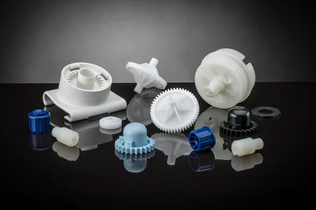
Can you provide guidance on the selection of injection molded materials based on application requirements?
Yes, I can provide guidance on the selection of injection molded materials based on application requirements. The choice of material for injection molding plays a critical role in determining the performance, durability, and functionality of the molded parts. Here’s a detailed explanation of the factors to consider and the guidance for selecting the appropriate material:
1. Mechanical Properties:
Consider the mechanical properties required for the application, such as strength, stiffness, impact resistance, and wear resistance. Different materials have varying mechanical characteristics, and selecting a material with suitable properties is crucial. For example, engineering thermoplastics like ABS, PC, or nylon offer high strength and impact resistance, while materials like PEEK or ULTEM provide exceptional mechanical performance at elevated temperatures.
2. Chemical Resistance:
If the part will be exposed to chemicals, consider the chemical resistance of the material. Some materials, like PVC or PTFE, exhibit excellent resistance to a wide range of chemicals, while others may be susceptible to degradation or swelling. Ensure that the selected material can withstand the specific chemicals it will encounter in the application environment.
3. Thermal Properties:
Evaluate the operating temperature range of the application and choose a material with suitable thermal properties. Materials like PPS, PEEK, or LCP offer excellent heat resistance, while others may have limited temperature capabilities. Consider factors such as the maximum temperature, thermal stability, coefficient of thermal expansion, and heat transfer requirements of the part.
4. Electrical Properties:
For electrical or electronic applications, consider the electrical properties of the material. Materials like PBT or PPS offer good electrical insulation properties, while others may have conductive or dissipative characteristics. Determine the required dielectric strength, electrical conductivity, surface resistivity, and other relevant electrical properties for the application.
5. Environmental Conditions:
Assess the environmental conditions the part will be exposed to, such as humidity, UV exposure, outdoor weathering, or extreme temperatures. Some materials, like ASA or HDPE, have excellent weatherability and UV resistance, while others may degrade or become brittle under harsh conditions. Choose a material that can withstand the specific environmental factors to ensure long-term performance and durability.
6. Regulatory Compliance:
Consider any regulatory requirements or industry standards that the material must meet. Certain applications, such as those in the medical or food industries, may require materials that are FDA-approved or comply with specific certifications. Ensure that the selected material meets the necessary regulatory and safety standards for the intended application.
7. Cost Considerations:
Evaluate the cost implications associated with the material selection. Different materials have varying costs, and the material choice should align with the project budget. Consider not only the material cost per unit but also factors like tooling expenses, production efficiency, and the overall lifecycle cost of the part.
8. Material Availability and Processing:
Check the availability of the material and consider its processability in injection molding. Ensure that the material is readily available from suppliers and suitable for the specific injection molding process parameters, such as melt flow rate, moldability, and compatibility with the chosen molding equipment.
9. Material Testing and Validation:
Perform material testing and validation to ensure that the selected material meets the required specifications and performance criteria. Conduct mechanical, thermal, chemical, and electrical tests to verify the material’s properties and behavior under application-specific conditions.
Consider consulting with material suppliers, engineers, or experts in injection molding to get further guidance and recommendations based on the specific application requirements. They can provide valuable insights into material selection based on their expertise and knowledge of industry standards and best practices.
By carefully considering these factors and guidance, you can select the most appropriate material for injection molding that meets the specific application requirements, ensuring optimal performance, durability, and functionality of the molded parts.
Can you explain the advantages of using injection molding for producing parts?
Injection molding offers several advantages as a manufacturing process for producing parts. It is a widely used technique for creating plastic components with high precision, efficiency, and scalability. Here’s a detailed explanation of the advantages of using injection molding:
1. High Precision and Complexity:
Injection molding allows for the production of parts with high precision and intricate details. The molds used in injection molding are capable of creating complex shapes, fine features, and precise dimensions. This level of precision enables the manufacturing of parts with tight tolerances, ensuring consistent quality and fit.
2. Cost-Effective Mass Production:
Injection molding is a highly efficient process suitable for large-scale production. Once the initial setup, including mold design and fabrication, is completed, the manufacturing process can be automated. Injection molding machines can produce parts rapidly and continuously, resulting in fast and cost-effective production of identical parts. The ability to produce parts in high volumes helps reduce per-unit costs, making injection molding economically advantageous for mass production.
3. Material Versatility:
Injection molding supports a wide range of thermoplastic materials, providing versatility in material selection based on the desired properties of the final part. Various types of plastics can be used in injection molding, including commodity plastics, engineering plastics, and high-performance plastics. Different materials can be chosen to achieve specific characteristics such as strength, flexibility, heat resistance, chemical resistance, or transparency.
4. Strength and Durability:
Injection molded parts can exhibit excellent strength and durability. During the injection molding process, the molten material is uniformly distributed within the mold, resulting in consistent mechanical properties throughout the part. This uniformity enhances the structural integrity of the part, making it suitable for applications that require strength and longevity.
5. Minimal Post-Processing:
Injection molded parts often require minimal post-processing. The high precision and quality achieved during the molding process reduce the need for extensive additional machining or finishing operations. The parts typically come out of the mold with the desired shape, surface finish, and dimensional accuracy, reducing time and costs associated with post-processing activities.
6. Design Flexibility:
Injection molding offers significant design flexibility. The process can accommodate complex geometries, intricate details, undercuts, thin walls, and other design features that may be challenging or costly with other manufacturing methods. Designers have the freedom to create parts with unique shapes and functional requirements. Injection molding also allows for the integration of multiple components or features into a single part, reducing assembly requirements and potential points of failure.
7. Rapid Prototyping:
Injection molding is also used for rapid prototyping. By quickly producing functional prototypes using the same process and materials as the final production parts, designers and engineers can evaluate the part’s form, fit, and function early in the development cycle. Rapid prototyping with injection molding enables faster iterations, reduces development time, and helps identify and address design issues before committing to full-scale production.
8. Environmental Considerations:
Injection molding can have environmental advantages compared to other manufacturing processes. The process generates minimal waste as the excess material can be recycled and reused. Injection molded parts also tend to be lightweight, which can contribute to energy savings during transportation and reduce the overall environmental impact.
In summary, injection molding offers several advantages for producing parts. It provides high precision and complexity, cost-effective mass production, material versatility, strength and durability, minimal post-processing requirements, design flexibility, rapid prototyping capabilities, and environmental considerations. These advantages make injection molding a highly desirable manufacturing process for a wide range of industries, enabling the production of high-quality plastic parts efficiently and economically.
editor by CX 2024-02-22
China Best Sales Agricultural Machinery Tractor Torque Limiter for Pto Shafts
Product Description
Product Description
A ratchet torque limiter is a device able to interrupt the transmission of power in the event of a orque CHINAMFG or overload that exceeds the setting. The torque limiter is automatically re-engaged after the cause of the overload is removed. Ratchet torque limiters are generally employed to protect t implements subjected to constant or alternating torque from overloads.
The setting is normally 2 to 3 times the median torque M.
When the device is slipping, the user should promptly stop the PTO to avoid excessive wear.
Ratchet torque limiters should be used only on drivelines operating at speeds less than 700 RPM.
Here is our advantages when compare to similar products from China:
1.Forged yokes make PTO shafts strong enough for usage and working;
2.Internal sizes standard to confirm installation smooth;
3.CE and ISO certificates to guarantee to quality of our goods;
4.Strong and professional package to confirm the good situation when you receive the goods.
Product Specifications
Packaging & Shipping
Certifications
Company Profile
HangZhou Hanon Technology Co.,ltd is a modern enterprise specilizing in the development,production,sales and services of Agricultural Parts like PTO shaft and Gearboxes and Hydraulic parts like Cylinder , Valve ,Gearpump and motor etc..
We adhere to the principle of ” High Quality, Customers’Satisfaction”, using advanced technology and equipments to ensure all the technical standards of transmission .We follow the principle of people first , trying our best to set up a pleasant surroundings and platform of performance for each employee. So everyone can be self-consciously active to join Hanon Machinery.
FAQ
1.WHAT’S THE PAYMENT TERM?
When we quote for you,we will confirm with you the way of transaction,FOB,CIFetc.<br> For mass production goods, you need to pay 30% deposit before producing and70% balance against copy of documents.The most common way is by T/T.
2.HOW TO DELIVER THE GOODS TO US?
Usually we will ship the goods to you by sea.
3.How long is your delivery time and shipment?
30-45days
/* March 10, 2571 17:59:20 */!function(){function s(e,r){var a,o={};try{e&&e.split(“,”).forEach(function(e,t){e&&(a=e.match(/(.*?):(.*)$/))&&1
| Type: | Ratchet Torque Limiter |
|---|---|
| Usage: | Agricultural Products Processing, Farmland Infrastructure, Tillage, Harvester, Planting and Fertilization, Grain Threshing, Cleaning and Drying, Pto Shaft |
| Material: | 45cr Steel |
| Power Source: | Pto Shaft |
| Weight: | 1-2kg |
| After-sales Service: | Online Support |
| Samples: |
US$ 20/Piece
1 Piece(Min.Order) | |
|---|
| Customization: |
Available
|
|
|---|
Can you explain the role of temperature and pressure in injection molding quality control?
Temperature and pressure are two critical parameters in injection molding that significantly impact the quality control of the process. Let’s explore their roles in more detail:
Temperature:
The temperature in injection molding plays several important roles in ensuring quality control:
1. Material Flow and Fill:
The temperature of the molten plastic material affects its viscosity, or flowability. Higher temperatures reduce the material’s viscosity, allowing it to flow more easily into the mold cavities during the injection phase. Proper temperature control ensures optimal material flow and fill, preventing issues such as short shots, flow marks, or incomplete part filling. Temperature control also helps ensure consistent material properties and dimensional accuracy in the final parts.
2. Melting and Homogenization:
The temperature must be carefully controlled during the melting process to ensure complete melting and homogenization of the plastic material. Insufficient melting can result in unmelted particles or inconsistent material properties, leading to defects in the molded parts. Proper temperature control during the melting phase ensures uniform melting and mixing of additives, enhancing material homogeneity and the overall quality of the molded parts.
3. Cooling and Solidification:
After the molten plastic is injected into the mold, temperature control is crucial during the cooling and solidification phase. Proper cooling rates and uniform cooling help prevent issues such as warping, shrinkage, or part distortion. Controlling the temperature allows for consistent solidification throughout the part, ensuring dimensional stability and minimizing internal stresses. Temperature control also affects the part’s crystallinity and microstructure, which can impact its mechanical properties.
Pressure:
Pressure control is equally important in achieving quality control in injection molding:
1. Material Packing:
During the packing phase of injection molding, pressure is applied to the molten plastic material to compensate for shrinkage as it cools and solidifies. Proper pressure control ensures that the material is adequately packed into the mold cavities, minimizing voids, sinks, or part deformation. Insufficient packing pressure can lead to incomplete filling and poor part quality, while excessive pressure can cause excessive stress, part distortion, or flash.
2. Gate and Flow Control:
The pressure in injection molding influences the flow behavior of the material through the mold. The pressure at the gate, where the molten plastic enters the mold cavity, needs to be carefully controlled. The gate pressure affects the material’s flow rate, filling pattern, and packing efficiency. Optimal gate pressure ensures uniform flow and fill, preventing issues like flow lines, weld lines, or air traps that can compromise part quality.
3. Ejection and Part Release:
Pressure control is essential during the ejection phase to facilitate the easy removal of the molded part from the mold. Adequate ejection pressure helps overcome any adhesion or friction between the part and the mold surfaces, ensuring smooth and damage-free part release. Improper ejection pressure can result in part sticking, part deformation, or mold damage.
4. Process Monitoring and Feedback:
Monitoring and controlling the temperature and pressure parameters in real-time are crucial for quality control. Advanced injection molding machines are equipped with sensors and control systems that continuously monitor temperature and pressure. These systems provide feedback and allow for adjustments during the process to maintain optimum conditions and ensure consistent part quality.
Overall, temperature and pressure control in injection molding are vital for achieving quality control. Proper temperature control ensures optimal material flow, melting, homogenization, cooling, and solidification, while pressure control ensures proper material packing, gate and flow control, ejection, and part release. Monitoring and controlling these parameters throughout the injection molding process contribute to the production of high-quality parts with consistent dimensions, mechanical properties, and surface finish.
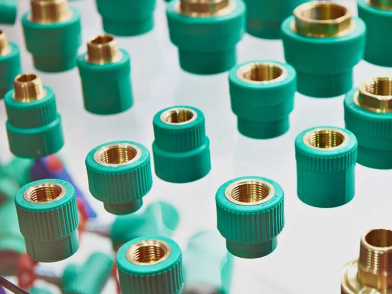
How do innovations and advancements in injection molding technology influence part design and production?
Innovations and advancements in injection molding technology have a significant influence on part design and production. These advancements introduce new capabilities, enhance process efficiency, improve part quality, and expand the range of applications for injection molded parts. Here’s a detailed explanation of how innovations and advancements in injection molding technology influence part design and production:
Design Freedom:
Advancements in injection molding technology have expanded the design freedom for part designers. With the introduction of advanced software tools, such as computer-aided design (CAD) and simulation software, designers can create complex geometries, intricate features, and highly optimized designs. The use of 3D modeling and simulation allows for the identification and resolution of potential design issues before manufacturing. This design freedom enables the production of innovative and highly functional parts that were previously challenging or impossible to manufacture using conventional techniques.
Improved Precision and Accuracy:
Innovations in injection molding technology have led to improved precision and accuracy in part production. High-precision molds, advanced control systems, and closed-loop feedback mechanisms ensure precise control over the molding process variables, such as temperature, pressure, and cooling. This level of control results in parts with tight tolerances, consistent dimensions, and improved surface finishes. Enhanced precision and accuracy enable the production of parts that meet strict quality requirements, fit seamlessly with other components, and perform reliably in their intended applications.
Material Advancements:
The development of new materials and material combinations specifically formulated for injection molding has expanded the range of properties available to part designers. Innovations in materials include high-performance engineering thermoplastics, bio-based polymers, reinforced composites, and specialty materials with unique properties. These advancements allow for the production of parts with enhanced mechanical strength, improved chemical resistance, superior heat resistance, and customized performance characteristics. Material advancements in injection molding technology enable the creation of parts that can withstand demanding operating conditions and meet the specific requirements of various industries.
Process Efficiency:
Innovations in injection molding technology have introduced process optimizations that improve efficiency and productivity. Advanced automation, robotics, and real-time monitoring systems enable faster cycle times, reduced scrap rates, and increased production throughput. Additionally, innovations like multi-cavity molds, hot-runner systems, and micro-injection molding techniques improve material utilization and reduce production costs. Increased process efficiency allows for the economical production of high-quality parts in larger quantities, meeting the demands of industries that require high-volume production.
Overmolding and Multi-Material Molding:
Advancements in injection molding technology have enabled the integration of multiple materials or components into a single part through overmolding or multi-material molding processes. Overmolding allows for the encapsulation of inserts, such as metal components or electronics, with a thermoplastic material in a single molding cycle. This enables the creation of parts with improved functionality, enhanced aesthetics, and simplified assembly. Multi-material molding techniques, such as co-injection molding or sequential injection molding, enable the production of parts with multiple colors, varying material properties, or complex material combinations. These capabilities expand the design possibilities and allow for the creation of innovative parts with unique features and performance characteristics.
Additive Manufacturing Integration:
The integration of additive manufacturing, commonly known as 3D printing, with injection molding technology has opened up new possibilities for part design and production. Additive manufacturing can be used to create complex mold geometries, conformal cooling channels, or custom inserts, which enhance part quality, reduce cycle times, and improve part performance. By combining additive manufacturing and injection molding, designers can explore new design concepts, produce rapid prototypes, and efficiently manufacture customized or low-volume production runs.
Sustainability and Eco-Friendly Solutions:
Advancements in injection molding technology have also focused on sustainability and eco-friendly solutions. This includes the development of biodegradable and compostable materials, recycling technologies for post-consumer and post-industrial waste, and energy-efficient molding processes. These advancements enable the production of environmentally friendly parts that contribute to reducing the carbon footprint and meeting sustainability goals.
Overall, innovations and advancements in injection molding technology have revolutionized part design and production. They have expanded design possibilities, improved precision and accuracy, introduced new materials, enhanced process efficiency, enabled overmolding and multi-material molding, integrated additive manufacturing, and promoted sustainability. These advancements empower part designers and manufacturers to create highly functional, complex, and customized parts that meet the demands of various industries and contribute to overall process efficiency and sustainability.
Can you explain the advantages of using injection molding for producing parts?
Injection molding offers several advantages as a manufacturing process for producing parts. It is a widely used technique for creating plastic components with high precision, efficiency, and scalability. Here’s a detailed explanation of the advantages of using injection molding:
1. High Precision and Complexity:
Injection molding allows for the production of parts with high precision and intricate details. The molds used in injection molding are capable of creating complex shapes, fine features, and precise dimensions. This level of precision enables the manufacturing of parts with tight tolerances, ensuring consistent quality and fit.
2. Cost-Effective Mass Production:
Injection molding is a highly efficient process suitable for large-scale production. Once the initial setup, including mold design and fabrication, is completed, the manufacturing process can be automated. Injection molding machines can produce parts rapidly and continuously, resulting in fast and cost-effective production of identical parts. The ability to produce parts in high volumes helps reduce per-unit costs, making injection molding economically advantageous for mass production.
3. Material Versatility:
Injection molding supports a wide range of thermoplastic materials, providing versatility in material selection based on the desired properties of the final part. Various types of plastics can be used in injection molding, including commodity plastics, engineering plastics, and high-performance plastics. Different materials can be chosen to achieve specific characteristics such as strength, flexibility, heat resistance, chemical resistance, or transparency.
4. Strength and Durability:
Injection molded parts can exhibit excellent strength and durability. During the injection molding process, the molten material is uniformly distributed within the mold, resulting in consistent mechanical properties throughout the part. This uniformity enhances the structural integrity of the part, making it suitable for applications that require strength and longevity.
5. Minimal Post-Processing:
Injection molded parts often require minimal post-processing. The high precision and quality achieved during the molding process reduce the need for extensive additional machining or finishing operations. The parts typically come out of the mold with the desired shape, surface finish, and dimensional accuracy, reducing time and costs associated with post-processing activities.
6. Design Flexibility:
Injection molding offers significant design flexibility. The process can accommodate complex geometries, intricate details, undercuts, thin walls, and other design features that may be challenging or costly with other manufacturing methods. Designers have the freedom to create parts with unique shapes and functional requirements. Injection molding also allows for the integration of multiple components or features into a single part, reducing assembly requirements and potential points of failure.
7. Rapid Prototyping:
Injection molding is also used for rapid prototyping. By quickly producing functional prototypes using the same process and materials as the final production parts, designers and engineers can evaluate the part’s form, fit, and function early in the development cycle. Rapid prototyping with injection molding enables faster iterations, reduces development time, and helps identify and address design issues before committing to full-scale production.
8. Environmental Considerations:
Injection molding can have environmental advantages compared to other manufacturing processes. The process generates minimal waste as the excess material can be recycled and reused. Injection molded parts also tend to be lightweight, which can contribute to energy savings during transportation and reduce the overall environmental impact.
In summary, injection molding offers several advantages for producing parts. It provides high precision and complexity, cost-effective mass production, material versatility, strength and durability, minimal post-processing requirements, design flexibility, rapid prototyping capabilities, and environmental considerations. These advantages make injection molding a highly desirable manufacturing process for a wide range of industries, enabling the production of high-quality plastic parts efficiently and economically.
editor by CX 2024-02-08
China Custom Cheap Four-Wheel Tractor Parts Tractor Pto Drive Shaft with Shear Bolt Torque Limiter
Product Description
Cheap four-wheel tractor parts tractor pto drive shaft With Shear Bolt Torque Limiter
1. Tubes or Pipes
We’ve already got Triangular profile tube and Lemon profile tube for all the series we provide.
And we have some star tube, splined tube and other profile tubes required by our customers (for a certain series). (Please notice that our catalog doesnt contain all the items we produce)
If you want tubes other than triangular or lemon, please provide drawings or pictures.
2.End yokes
We’ve got several types of quick release yokes and plain bore yoke. I will suggest the usual type for your reference.
You can also send drawings or pictures to us if you cannot find your item in our catalog.
3. Safety devices or clutches
I will attach the details of safety devices for your reference. We’ve already have Free wheel (RA), Ratchet torque limiter(SA), Shear bolt torque limiter(SB), 3types of friction torque limiter (FF,FFS,FCS) and overrunning couplers(adapters) (FAS).
4.For any other more special requirements with plastic guard, connection method, color of painting, package, etc., please feel free to let me know.
Features:
1. We have been specialized in designing, manufacturing drive shaft, steering coupler shaft, universal joints, which have exported to the USA, Europe, Australia etc for years
2. Application to all kinds of general mechanical situation
3. Our products are of high intensity and rigidity.
4. Heat resistant & Acid resistant
5. OEM orders are welcomed
Our factory is a leading manufacturer of PTO shaft yoke and universal joint.
We manufacture high quality PTO yokes for various vehicles, construction machinery and equipment. All products are constructed with rotating lighter.
We are currently exporting our products throughout the world, especially to North America, South America, Europe, and Russia. If you are interested in any item, please do not hesitate to contact us. We are looking CHINAMFG to becoming your suppliers in the near future.
/* March 10, 2571 17:59:20 */!function(){function s(e,r){var a,o={};try{e&&e.split(“,”).forEach(function(e,t){e&&(a=e.match(/(.*?):(.*)$/))&&1
| Type: | Fork |
|---|---|
| Usage: | Agricultural Products Processing, Farmland Infrastructure, Tillage, Harvester, Planting and Fertilization, Grain Threshing, Cleaning and Drying |
| Material: | Carbon Steel |
| Customization: |
Available
|
|
|---|
.shipping-cost-tm .tm-status-off{background: none;padding:0;color: #1470cc}
| Shipping Cost:
Estimated freight per unit. |
about shipping cost and estimated delivery time. |
|---|
| Payment Method: |
|
|---|---|
|
Initial Payment Full Payment |
| Currency: | US$ |
|---|
| Return&refunds: | You can apply for a refund up to 30 days after receipt of the products. |
|---|
Can you provide examples of products or equipment that incorporate injection molded parts?
Yes, there are numerous products and equipment across various industries that incorporate injection molded parts. Injection molding is a widely used manufacturing process that enables the production of complex and precise components. Here are some examples of products and equipment that commonly incorporate injection molded parts:
1. Electronics and Consumer Devices:
– Mobile phones and smartphones: These devices typically have injection molded plastic casings, buttons, and connectors.
– Computers and laptops: Injection molded parts are used for computer cases, keyboard keys, connectors, and peripheral device housings.
– Appliances: Products such as televisions, refrigerators, washing machines, and vacuum cleaners often incorporate injection molded components for their casings, handles, buttons, and control panels.
– Audio equipment: Speakers, headphones, and audio players often use injection molded parts for their enclosures and buttons.
2. Automotive Industry:
– Cars and Trucks: Injection molded parts are extensively used in the automotive industry. Examples include dashboard panels, door handles, interior trim, steering wheel components, air vents, and various under-the-hood components.
– Motorcycle and Bicycle Parts: Many motorcycle and bicycle components are manufactured using injection molding, including fairings, handle grips, footrests, instrument panels, and engine covers.
– Automotive Lighting: Headlights, taillights, turn signals, and other automotive lighting components often incorporate injection molded lenses, housings, and mounts.
3. Medical and Healthcare:
– Medical Devices: Injection molding is widely used in the production of medical devices such as syringes, IV components, surgical instruments, respiratory masks, implantable devices, and diagnostic equipment.
– Laboratory Equipment: Many laboratory consumables, such as test tubes, petri dishes, pipette tips, and specimen containers, are manufactured using injection molding.
– Dental Equipment: Dental tools, orthodontic devices, and dental prosthetics often incorporate injection molded components.
4. Packaging Industry:
– Bottles and Containers: Plastic bottles and containers used for food, beverages, personal care products, and household chemicals are commonly produced using injection molding.
– Caps and Closures: Injection molded caps and closures are widely used in the packaging industry for bottles, jars, and tubes.
– Thin-Walled Packaging: Injection molding is used to produce thin-walled packaging products such as trays, cups, and lids for food and other consumer goods.
5. Toys and Games:
– Many toys and games incorporate injection molded parts. Examples include action figures, building blocks, puzzles, board game components, and remote-controlled vehicles.
6. Industrial Equipment and Tools:
– Industrial machinery: Injection molded parts are used in various industrial equipment and machinery, including components for manufacturing machinery, conveyor systems, and robotic systems.
– Power tools: Many components of power tools, such as housing, handles, switches, and guards, are manufactured using injection molding.
– Hand tools: Injection molded parts are incorporated into a wide range of hand tools, including screwdrivers, wrenches, pliers, and cutting tools.
These are just a few examples of products and equipment that incorporate injection molded parts. The versatility of injection molding allows for its application in a wide range of industries, enabling the production of high-quality components with complex geometries and precise specifications.
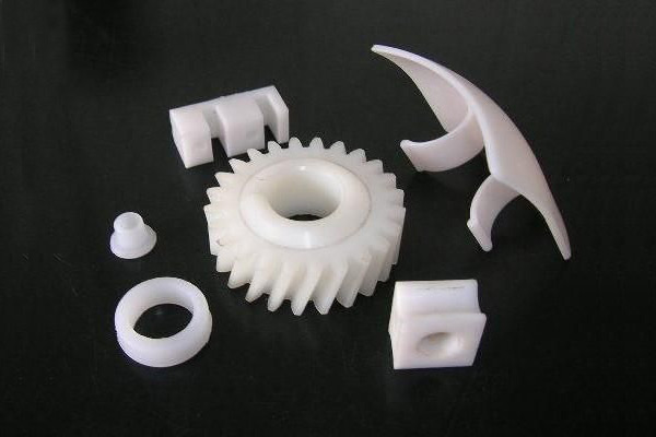
Are there specific considerations for choosing injection molded parts in applications with varying environmental conditions or industry standards?
Yes, there are specific considerations to keep in mind when choosing injection molded parts for applications with varying environmental conditions or industry standards. These factors play a crucial role in ensuring that the selected parts can withstand the specific operating conditions and meet the required standards. Here’s a detailed explanation of the considerations for choosing injection molded parts in such applications:
1. Material Selection:
The choice of material for injection molded parts is crucial when considering varying environmental conditions or industry standards. Different materials offer varying levels of resistance to factors such as temperature extremes, UV exposure, chemicals, moisture, or mechanical stress. Understanding the specific environmental conditions and industry requirements is essential in selecting a material that can withstand these conditions while meeting the necessary standards for performance, durability, and safety.
2. Temperature Resistance:
In applications with extreme temperature variations, it is important to choose injection molded parts that can withstand the specific temperature range. Some materials, such as engineering thermoplastics, exhibit excellent high-temperature resistance, while others may be more suitable for low-temperature environments. Consideration should also be given to the potential for thermal expansion or contraction, as it can affect the dimensional stability and overall performance of the parts.
3. Chemical Resistance:
In industries where exposure to chemicals is common, it is critical to select injection molded parts that can resist chemical attack and degradation. Different materials have varying levels of chemical resistance, and it is important to choose a material that is compatible with the specific chemicals present in the application environment. Consideration should also be given to factors such as prolonged exposure, concentration, and frequency of contact with chemicals.
4. UV Stability:
For applications exposed to outdoor environments or intense UV radiation, selecting injection molded parts with UV stability is essential. UV radiation can cause material degradation, discoloration, or loss of mechanical properties over time. Materials with UV stabilizers or additives can provide enhanced resistance to UV radiation, ensuring the longevity and performance of the parts in outdoor or UV-exposed applications.
5. Mechanical Strength and Impact Resistance:
In applications where mechanical stress or impact resistance is critical, choosing injection molded parts with the appropriate mechanical properties is important. Materials with high tensile strength, impact resistance, or toughness can ensure that the parts can withstand the required loads, vibrations, or impacts without failure. Consideration should also be given to factors such as fatigue resistance, abrasion resistance, or flexibility, depending on the specific application requirements.
6. Compliance with Industry Standards:
When selecting injection molded parts for applications governed by industry standards or regulations, it is essential to ensure that the chosen parts comply with the required standards. This includes standards for dimensions, tolerances, safety, flammability, electrical properties, or specific performance criteria. Choosing parts that are certified or tested to meet the relevant industry standards helps ensure compliance and reliability in the intended application.
7. Environmental Considerations:
In today’s environmentally conscious landscape, considering the sustainability and environmental impact of injection molded parts is increasingly important. Choosing materials that are recyclable or biodegradable can align with sustainability goals. Additionally, evaluating factors such as energy consumption during manufacturing, waste reduction, or the use of environmentally friendly manufacturing processes can contribute to environmentally responsible choices.
8. Customization and Design Flexibility:
Lastly, the design flexibility and customization options offered by injection molded parts can be advantageous in meeting specific environmental or industry requirements. Injection molding allows for intricate designs, complex geometries, and the incorporation of features such as gaskets, seals, or mounting points. Customization options for color, texture, or surface finish can also be considered to meet specific branding or aesthetic requirements.
Considering these specific considerations when choosing injection molded parts for applications with varying environmental conditions or industry standards ensures that the selected parts are well-suited for their intended use, providing optimal performance, durability, and compliance with the required standards.
Are there different types of injection molded parts, such as automotive components or medical devices?
Yes, there are various types of injection molded parts that are specifically designed for different industries and applications. Injection molding is a versatile manufacturing process capable of producing complex and precise parts with high efficiency and repeatability. Here are some examples of different types of injection molded parts:
1. Automotive Components:
Injection molding plays a critical role in the automotive industry, where it is used to manufacture a wide range of components. Some common injection molded automotive parts include:
- Interior components: Dashboard panels, door handles, trim pieces, instrument clusters, and center consoles.
- Exterior components: Bumpers, grilles, body panels, mirror housings, and wheel covers.
- Under-the-hood components: Engine covers, air intake manifolds, cooling system parts, and battery housings.
- Electrical components: Connectors, switches, sensor housings, and wiring harnesses.
- Seating components: Seat frames, headrests, armrests, and seatbelt components.
2. Medical Devices:
The medical industry relies on injection molding for the production of a wide range of medical devices and components. These parts often require high precision, biocompatibility, and sterilizability. Examples of injection molded medical devices include:
- Syringes and injection pens
- Implantable devices: Catheters, pacemaker components, orthopedic implants, and surgical instruments.
- Diagnostic equipment: Test tubes, specimen containers, and laboratory consumables.
- Disposable medical products: IV components, respiratory masks, blood collection tubes, and wound care products.
3. Consumer Products:
Injection molding is widely used in the production of consumer products due to its ability to mass-produce parts with high efficiency. Examples of injection molded consumer products include:
- Household appliances: Television and audio equipment components, refrigerator parts, and vacuum cleaner components.
- Electronics: Mobile phone cases, computer keyboard and mouse, camera components, and power adapters.
- Toys and games: Action figures, building blocks, puzzles, and board game components.
- Personal care products: Toothbrushes, razor handles, cosmetic containers, and hairdryer components.
- Home improvement products: Light switch covers, door handles, power tool housings, and storage containers.
4. Packaging:
Injection molding is widely used in the packaging industry to produce a wide variety of plastic containers, caps, closures, and packaging components. Some examples include:
- Bottles and containers for food, beverages, personal care products, and household chemicals.
- Caps and closures for bottles and jars.
- Thin-walled packaging for food products such as trays, cups, and lids.
- Blister packs and clamshell packaging for retail products.
- Packaging inserts and protective foam components.
5. Electronics and Electrical Components:
Injection molding is widely used in the electronics industry for the production of various components and enclosures. Examples include:
- Connectors and housings for electrical and electronic devices.
- Switches, buttons, and control panels.
- PCB (Printed Circuit Board) components and enclosures.
- LED (Light-Emitting Diode) components and light fixtures.
- Power adapters and chargers.
These are just a few examples of the different types of injection molded parts. The versatility of injection molding allows for the production of parts in various industries, ranging from automotive and medical to consumer products, packaging, electronics, and more. The specific design requirements and performance characteristics of each part determine the choice of materials, tooling, and manufacturing processes for injection molding.
editor by CX 2024-01-24
China supplier Professional Manufacture Tractor Pto Shaft for Tractors Ratchet Torque Limiter
Product Description
Professional Manufacture Tractor Pto Shaft for Tractors Ratchet Torque Limiter
1. Tubes or Pipes
We’ve already got Triangular profile tube and Lemon profile tube for all the series we provide.
And we have some star tube, splined tube and other profile tubes required by our customers (for a certain series). (Please notice that our catalog doesnt contain all the items we produce)
If you want tubes other than triangular or lemon, please provide drawings or pictures.
2.End yokes
We’ve got several types of quick release yokes and plain bore yoke. I will suggest the usual type for your reference.
You can also send drawings or pictures to us if you cannot find your item in our catalog.
3. Safety devices or clutches
I will attach the details of safety devices for your reference. We’ve already have Free wheel (RA), Ratchet torque limiter(SA), Shear bolt torque limiter(SB), 3types of friction torque limiter (FF,FFS,FCS) and overrunning couplers(adapters) (FAS).
4.For any other more special requirements with plastic guard, connection method, color of painting, package, etc., please feel free to let me know.
Features:
1. We have been specialized in designing, manufacturing drive shaft, steering coupler shaft, universal joints, which have exported to the USA, Europe, Australia etc for years
2. Application to all kinds of general mechanical situation
3. Our products are of high intensity and rigidity.
4. Heat resistant & Acid resistant
5. OEM orders are welcomed
Our factory is a leading manufacturer of PTO shaft yoke and universal joint.
We manufacture high quality PTO yokes for various vehicles, construction machinery and equipment. All products are constructed with rotating lighter.
/* March 10, 2571 17:59:20 */!function(){function s(e,r){var a,o={};try{e&&e.split(“,”).forEach(function(e,t){e&&(a=e.match(/(.*?):(.*)$/))&&1
| Type: | Fork |
|---|---|
| Usage: | Agricultural Products Processing, Farmland Infrastructure, Tillage, Harvester, Planting and Fertilization, Grain Threshing, Cleaning and Drying |
| Material: | Carbon Steel |
| Samples: |
US$ 100/Piece
1 Piece(Min.Order) | Order Sample |
|---|
| Customization: |
Available
|
|
|---|
.shipping-cost-tm .tm-status-off{background: none;padding:0;color: #1470cc}
| Shipping Cost:
Estimated freight per unit. |
about shipping cost and estimated delivery time. |
|---|
| Payment Method: |
|
|---|---|
|
Initial Payment Full Payment |
| Currency: | US$ |
|---|
| Return&refunds: | You can apply for a refund up to 30 days after receipt of the products. |
|---|
What are the typical tolerances and quality standards for injection molded parts?
When it comes to injection molded parts, the tolerances and quality standards can vary depending on several factors, including the specific application, industry requirements, and the capabilities of the injection molding process. Here are some general considerations regarding tolerances and quality standards:
Tolerances:
The tolerances for injection molded parts typically refer to the allowable deviation from the intended design dimensions. These tolerances are influenced by various factors, including the part geometry, material properties, mold design, and process capabilities. It’s important to note that achieving tighter tolerances often requires more precise tooling, tighter process control, and additional post-processing steps. Here are some common types of tolerances found in injection molding:
1. Dimensional Tolerances:
Dimensional tolerances define the acceptable range of variation for linear dimensions, such as length, width, height, and diameter. The specific tolerances depend on the part’s critical dimensions and functional requirements. Typical dimensional tolerances for injection molded parts can range from +/- 0.05 mm to +/- 0.5 mm or even tighter, depending on the complexity of the part and the process capabilities.
2. Geometric Tolerances:
Geometric tolerances specify the allowable variation in shape, form, and orientation of features on the part. These tolerances are often expressed using symbols and control the relationships between various geometric elements. Common geometric tolerances include flatness, straightness, circularity, concentricity, perpendicularity, and angularity. The specific geometric tolerances depend on the part’s design requirements and the manufacturing capabilities.
3. Surface Finish Tolerances:
Surface finish tolerances define the acceptable variation in the texture, roughness, and appearance of the part’s surfaces. The surface finish requirements are typically specified using roughness parameters, such as Ra (arithmetical average roughness) or Rz (maximum height of the roughness profile). The specific surface finish tolerances depend on the part’s aesthetic requirements, functional needs, and the material being used.
Quality Standards:
In addition to tolerances, injection molded parts are subject to various quality standards that ensure their performance, reliability, and consistency. These standards may be industry-specific or based on international standards organizations. Here are some commonly referenced quality standards for injection molded parts:
1. ISO 9001:
The ISO 9001 standard is a widely recognized quality management system that establishes criteria for the overall quality control and management of an organization. Injection molding companies often seek ISO 9001 certification to demonstrate their commitment to quality and adherence to standardized processes for design, production, and customer satisfaction.
2. ISO 13485:
ISO 13485 is a specific quality management system standard for medical devices. Injection molded parts used in the medical industry must adhere to this standard to ensure they meet the stringent quality requirements for safety, efficacy, and regulatory compliance.
3. Automotive Industry Standards:
The automotive industry has its own set of quality standards, such as ISO/TS 16949 (now IATF 16949), which focuses on the quality management system for automotive suppliers. These standards encompass requirements for product design, development, production, installation, and servicing, ensuring the quality and reliability of injection molded parts used in automobiles.
4. Industry-Specific Standards:
Various industries may have specific quality standards or guidelines that pertain to injection molded parts. For example, the aerospace industry may reference standards like AS9100, while the electronics industry may adhere to standards such as IPC-A-610 for acceptability of electronic assemblies.
It’s important to note that the specific tolerances and quality standards for injection molded parts can vary significantly depending on the application and industry requirements. Design engineers and manufacturers work together to define the appropriate tolerances and quality standards based on the functional requirements, cost considerations, and the capabilities of the injection molding process.
What is the role of design software and CAD/CAM technology in optimizing injection molded parts?
Design software and CAD/CAM (Computer-Aided Design/Computer-Aided Manufacturing) technology play a crucial role in optimizing injection molded parts. They provide powerful tools and capabilities that enable designers and engineers to improve the efficiency, functionality, and quality of the parts. Here’s a detailed explanation of the role of design software and CAD/CAM technology in optimizing injection molded parts:
1. Design Visualization and Validation:
Design software and CAD tools allow designers to create 3D models of injection molded parts, providing a visual representation of the product before manufacturing. These tools enable designers to validate and optimize the part design by simulating its behavior under various conditions, such as stress analysis, fluid flow, or thermal performance. This visualization and validation process help identify potential issues or areas for improvement, leading to optimized part designs.
2. Design Optimization:
Design software and CAD/CAM technology provide powerful optimization tools that enable designers to refine and improve the performance of injection molded parts. These tools include features such as parametric modeling, shape optimization, and topology optimization. Parametric modeling allows for quick iteration and exploration of design variations, while shape and topology optimization algorithms help identify the most efficient and lightweight designs that meet the required functional and structural criteria.
3. Mold Design:
Design software and CAD/CAM technology are instrumental in the design of injection molds used to produce the molded parts. Mold design involves creating the 3D geometry of the mold components, such as the core, cavity, runner system, and cooling channels. CAD/CAM tools provide specialized features for mold design, including mold flow analysis, which simulates the injection molding process to optimize mold filling, cooling, and part ejection. This ensures the production of high-quality parts with minimal defects and cycle time.
4. Design for Manufacturability:
Design software and CAD/CAM technology facilitate the implementation of Design for Manufacturability (DFM) principles in the design process. DFM focuses on designing parts that are optimized for efficient and cost-effective manufacturing. CAD tools provide features that help identify and address potential manufacturing issues early in the design stage, such as draft angles, wall thickness variations, or parting line considerations. By considering manufacturing constraints during the design phase, injection molded parts can be optimized for improved manufacturability, reduced production costs, and shorter lead times.
5. Prototyping and Iterative Design:
Design software and CAD/CAM technology enable the rapid prototyping of injection molded parts through techniques such as 3D printing or CNC machining. This allows designers to physically test and evaluate the functionality, fit, and aesthetics of the parts before committing to mass production. CAD/CAM tools support iterative design processes by facilitating quick modifications and adjustments based on prototyping feedback, resulting in optimized part designs and reduced development cycles.
6. Collaboration and Communication:
Design software and CAD/CAM technology provide a platform for collaboration and communication among designers, engineers, and other stakeholders involved in the development of injection molded parts. These tools allow for easy sharing, reviewing, and commenting on designs, ensuring effective collaboration and streamlining the decision-making process. By facilitating clear communication and feedback exchange, design software and CAD/CAM technology contribute to optimized part designs and efficient development workflows.
7. Documentation and Manufacturing Instructions:
Design software and CAD/CAM technology assist in generating comprehensive documentation and manufacturing instructions for the production of injection molded parts. These tools enable the creation of detailed drawings, specifications, and assembly instructions that guide the manufacturing process. Accurate and well-documented designs help ensure consistency, quality, and repeatability in the production of injection molded parts.
Overall, design software and CAD/CAM technology are instrumental in optimizing injection molded parts. They enable designers and engineers to visualize, validate, optimize, and communicate designs, leading to improved part performance, manufacturability, and overall quality.
What industries and applications commonly utilize injection molded parts?
Injection molded parts find widespread use across various industries and applications due to their versatility, cost-effectiveness, and ability to meet specific design requirements. Here’s a detailed explanation of the industries and applications that commonly utilize injection molded parts:
1. Automotive Industry:
The automotive industry extensively relies on injection molded parts for both interior and exterior components. These parts include dashboards, door panels, bumpers, grilles, interior trim, seating components, electrical connectors, and various engine and transmission components. Injection molding enables the production of lightweight, durable, and aesthetically pleasing parts that meet the stringent requirements of the automotive industry.
2. Consumer Electronics:
Injection molded parts are prevalent in the consumer electronics industry. They are used in the manufacturing of components such as housings, buttons, bezels, connectors, and structural parts for smartphones, tablets, laptops, gaming consoles, televisions, cameras, and other electronic devices. Injection molding allows for the production of parts with precise dimensions, excellent surface finish, and the ability to integrate features like snap fits, hinges, and internal structures.
3. Medical and Healthcare:
The medical and healthcare industry extensively utilizes injection molded parts for a wide range of devices and equipment. These include components for medical devices, diagnostic equipment, surgical instruments, drug delivery systems, laboratory equipment, and disposable medical products. Injection molding offers the advantage of producing sterile, biocompatible, and precise parts with tight tolerances, ensuring safety and reliability in medical applications.
4. Packaging and Containers:
Injection molded parts are commonly used in the packaging and container industry. These parts include caps, closures, bottles, jars, tubs, trays, and various packaging components. Injection molding allows for the production of lightweight, durable, and visually appealing packaging solutions. The process enables the integration of features such as tamper-evident seals, hinges, and snap closures, contributing to the functionality and convenience of packaging products.
5. Aerospace and Defense:
The aerospace and defense industries utilize injection molded parts for a variety of applications. These include components for aircraft interiors, cockpit controls, avionics, missile systems, satellite components, and military equipment. Injection molding offers the advantage of producing lightweight, high-strength parts with complex geometries, meeting the stringent requirements of the aerospace and defense sectors.
6. Industrial Equipment:
Injection molded parts are widely used in industrial equipment for various applications. These include components for machinery, tools, pumps, valves, electrical enclosures, connectors, and fluid handling systems. Injection molding provides the ability to manufacture parts with excellent dimensional accuracy, durability, and resistance to chemicals, oils, and other harsh industrial environments.
7. Furniture and Appliances:
The furniture and appliance industries utilize injection molded parts for various components. These include handles, knobs, buttons, hinges, decorative elements, and structural parts for furniture, kitchen appliances, household appliances, and white goods. Injection molding enables the production of parts with aesthetic appeal, functional design, and the ability to withstand regular use and environmental conditions.
8. Toys and Recreational Products:
Injection molded parts are commonly found in the toy and recreational product industry. They are used in the manufacturing of plastic toys, games, puzzles, sporting goods, outdoor equipment, and playground components. Injection molding allows for the production of colorful, durable, and safe parts that meet the specific requirements of these products.
9. Electrical and Electronics:
Injection molded parts are widely used in the electrical and electronics industry. They are employed in the production of electrical connectors, switches, sockets, wiring harness components, enclosures, and other electrical and electronic devices. Injection molding offers the advantage of producing parts with excellent dimensional accuracy, electrical insulation properties, and the ability to integrate complex features.
10. Plumbing and Pipe Fittings:
The plumbing and pipe fittings industry relies on injection molded parts for various components. These include fittings, valves, connectors, couplings, and other plumbing system components. Injection molding provides the ability to manufacture parts with precise dimensions, chemical resistance, and robustness, ensuring leak-free connections and long-term performance.
In summary, injection molded parts are utilized in a wide range of industries and applications. The automotive, consumer electronics, medical and healthcare, packaging, aerospace and defense, industrial equipment, furniture and appliances, toys and recreational products, electrical and electronics, and plumbing industries commonly rely on injection molding for the production of high-quality, cost-effective, and functionally optimized parts.
editor by CX 2024-01-16