Product Description
CHINAMFG Keyless Locking Devices are used in rotating machinery, producing clamping pressure between surface of locking device and shaft to create adjustable and releasable mechanical connection, so as to clamp gears, pulleys and other components to a shaft without threads or keys.
Raw materials available in:
l Steel C45E,
l Steel 42CrMo4V
l Stainless Steel AISI431,
l Stainless Steel AISI304
Features:
1. Connect hubs solidly to shafts
2. Easy installation and disassembly
3. High torque transmission
4. Long lifetime and easy maintenance
5. Low notching effect
6. Reduction of wear and tear of expensive machine components
Ubet Machinery provides types of Keyless Locking Devices, which are interchangeable with many European and American brands. High quality always comes the first
Ubet Keyless Locking Device KLD-1
Medium torque, not self-centering, Medium surface pressures, No axial hub movement, flexible use, machining tolerance shaft H8, hub H8; socket head locking screw DIN912-12.9.
The most popular type of all KLD Locking Device, CHINAMFG Connection; the slotted design of the double tapered rings enables relatively high mounting tolerance, The large taper angles are not self-locking and facilitate the release of the connection
KLD-1 Interchange with Z2,BIKON 4000,BEA BK40,BONFIX CCE2000,Challenge 01,Chiaravalli RCK40,CONEX A, Fenlock FLK200,ITALBLOCK CN210,KTR100,KINLOK LOK30,KBS40,KANA 200,MAV 2005,POGGI CAL-A,RFN7012,Ringspann RLK200,Ringblok 1120,SIT 1,SATI KLGG,TOLLOK TLK200,Tsubaki AS,TAS3571,V-Blok VK400,Walther CHINAMFG MLC 1000,Fenner Drive B-Loc B400,LoveJoy SLD1500, FX10,OKBS40,DRIVELOCK40
Ubet Keyless Locking Assembly KLD-2
Medium torque, self-centering, small cross section, machining tolerance shaft H8, hub H8; Socket head locking screw DIN912-12.9
Self-centering with excellent concentricity; the small outer diameter is space-saving and suitable for small wheel diameters; the spacer ring between the outer flange and the hub maintains the fitting position in the axial direction to enable exact positioning without a shaft collar; the push-off threads in the outer flanges are used for dismantling.
KLD-2 Interchange with Z11,BIKON 8000,BEA BK80,BONFIX CCE1000,Challenge 02,Chiaravalli RCK80,CONEX B,7110 ECOLOC, Fenlock FLK110,GERWAH PSV2571.1,ITALBLOCK CN55,KTR250,KINLOK LOK10,KBS80,MAV 5061,POGGI CAL-B,RFN7110,Ringspann RLK110,Ringblok 1100,SIT 3,SATI KLCC,TOLLOK TLK110,Tsubaki TF,V-Blok VB800B,Walther CHINAMFG MLC3000,Fenner Drive B-Loc B800,LoveJoy SLD1900, FX20,OKBS80,DRIVELOCK80
Ubet Locking Elements KLD-3
Low torque, Medium surface pressure, Taper rings only, Low axial and radial dimensions
This clamping set is self-centering with excellent concentricity. The extremely small outer diameter is space-saving and suitable for small wheel diameters. The spacer ring between the outer flange and the hub maintains the fitting position in the axial direction to enable exact positioning without a shaft collar. The push-off threads in the outer flanges are used for dismantling.
KLD-3 Interchange with Z1,BIKON 5000,BEA BK50,BONFIX CCE3000,Challenge 03 Chiaravalli RCK50,CONEX C,Fenlock FLK300,ITALBLOCK CN31,KRT150,KINLOK LOK80,KBS50,KANA 300,MAV 3003,POGGI CAL-C,RFN8006,Ringspann RLK300,Ringblok 1060,SIT 2,SATI KLNN,TOLLOK TLK300,Tsubaki EL, ,Walther CHINAMFG MLC 2000,Fenner Drive B-Loc B112,LoveJoy SLD350, FX30,OKBS50,DRIVELOCK50
Ubet Mechanical Locking Device KLD-4
High torque, self-centering, medium surface pressure, machining tolerance shaft H8, hub H8; socket head Locking screw DIN912-12.9
KLD-4 Interchange with Z3,BIKON 7000A,BEA BK70,BONFIX CCE4000,Challenge 04,Chiaravalli RCK70,CONEX D,7004 ECOLOC, Fenlock FLK130,GERWAH PSV2007,ITALBLOCK CN54/N,KTR200,KINLOK LOK20A,KBS70,MAV 6901,POGGI CAL-D,RFN7013.0,Ringspann RLK130,Ringblok 1300.1,SIT 5A,SATI KLDA,TOLLOK TLK130,V-Blok VK700, FX40,OKBS70,DRIVELOCK70
Ubet Shaft Hub Connection KLD-5
Medium torque, reduced length, medium self-centering, High surface pressure, machining tolerance shaft H8, hub H8; socket head Locking screw DIN912-12.9
Suitable for narrow, disk-shaped wheel hubs. Self-centering and self-locking in the clamping state.
KLD-5 Interchange with Z3B,BIKON 1003,BEA BK13,BONFIX CCE4100,Challenge 05,Chiaravalli RCK13,CONEX DS,7003 ECOLOC, Fenlock FLK132,GERWAH PSV2006,KTR203,KBS13,KANA 201,MAV 1062,POGGI CAL-DS,RFN7013.0, Ringspann RLK132,Ringblok 1710,SIT 6,SATI KLAA,TOLLOK TLK132,TAS3003, V-Blok VK160,Walther CHINAMFG MLC 5006,LoveJoy SLD1750,FX41, OKBS13, DRIVELOCK13.
Ubet Shaft Locking Device KLD-6
Medium torque, self-centering, Low surface pressure, No axial hub movement, machining tolerance shaft H8, hub H8; socket head Locking screw DIN912-12.9
KLD-6 Interchange with Z13,BIKON 7000B,BEA BK71,BONFIX CCE4500,Challenge 06,Chiaravalli RCK71,CONEX E,7007 ECOLOC, Fenlock FLK131,GERWAH PSV2007.3,ITALBLOCK CN54/S,KTR201,KINLOK LOK20B,KBS71,MAV 6902,POGGI CAL-E,RFN7013.1,Ringspann RLK131,Ringblok 1300.2,SIT 5B,SATI KLDB,TOLLOK TLK131,Tsubaki KE,V-Blok VK700.1,Walther CHINAMFG MLC5000B, FX50,OKBS71,DRIVELOCK71
Ubet Clamping Power Lock KLD-7
Medium torque, reduced length, High surface pressure, No axial hub movement, machining tolerance shaft H8, hub H8; socket head Locking screw DIN912-12.9; Simultaneous Connection of Chain Sprocket
KLD-7 Interchange with Z8,BIKON 1006,BEA BK16,BONFIX CCE4600,Challenge 07,Chiaravalli RCK16,CONEX ES,7006 ECOLOC,Fenlock FLK133,GERWAH PSV2006.3,ITALBLOCK CN9/4,KTR206,KBS16,KANA 201,MAV 1061,POGGI CAL-ES,RFN7013.1,Ringspann RLK133,Ringblok 1720,SATI KLAB,TOLLOK TLK133,Tsubaki AE,TAS3006,V-Blok VK130,Walther CHINAMFG MLC 5007,LoveJoy SLD1750, FX51,OKBS16,DRIVELOCK16
Ubet Shrink Disc KLD-14
High torque, No axial hub movement, High speed application, preferred solution for coupling hub and hollow shaft gearbox, DIN931-10.9 screw; Smart-Lock Shrink Disc, Narrow Hub Connection for sprockets, connect hollow and CHINAMFG shafts frictionally and backlash-free.
KLD-14 Interchange with Z7B,BEA BK19,BONFIX CCE8000,Challenge 14,Chiaravalli RCK19,CONEX SD, Fenlock FLK603, ,KTR603,KBS19,MAV 2008,RFN4071,Ringspann RLK603,Ringblok 2200,SATI KLDD,TOLLOK TLK603, Tsubaki SL, ,Walther CHINAMFG MLC 9050,Fenner Drive B-Loc SD10,LoveJoy SLD900, FX190,OKBS19,DRIVELOCK19
Ubet Locking Assembly KLD-15
High torque, self-centering, Low-medium surface pressure, machining tolerance shaft H8, hub H8; socket head Locking screw DIN912-12.9
KLD-15 Interchange with BEA BK15, Challenge 15,Chiaravalli RCK15,CONEX EP, Fenlock FLK134,KBS15 ,MAV 3061,Ringspann RLK134,SATI KLBB,TOLLOK TLK134, FX52,DRIVELOCK15
Ubet Locking Bushes KLD-16
Medium torque, Reduced length, Medium self-centering, High surface pressure, machining tolerance shaft H8, hub H8; socket head Locking screw DIN912-12.9
KLD-16 Interchange with BONFIX CCE4900,Challenge 16,CONEX L,KTR225,KBS52,SATI KLHH, FX120
Ubet Ball Bearing Adapter Sleeve KLD-17
Low torque, Short Length, Not self-centering, Low surface pressure, machining tolerance shaft H8, hub H8
KLD-17 Interchange with BEA BK25, Challenge 17, KBS51, SATI KLFC, FX80
Ubet Bearing Adapter Sleeve KLD-17.1
Low-medium torque, self-centering, low surface pressure, machining tolerance shaft H8, hub H8
KLD-17.1 Interchange with Z19B, BEA BK26,Challenge 21,Chiaravalli RCK55, Fenlock FLK250,KTR125,KBS55, POGGI CAL-L,Ringspann RLK250,Ringblok 1500, SATI KLFF,TOLLOK TLK250
Ubet Shaft Clamping Collar KLD-18
Low-medium torque, Short Length, self-centering, low surface pressure, machining tolerance shaft H8, hub H8, socket head Locking screw DIN912-12.9
This clamping set is self-centering and suitable for extremely small shaft diameters. It transfers average to large torques
KLD-17.1 Interchange with BEA BK61,Chiaravalli RCK61,7002 ECOLOC ,GERWAH PSV2061,KTR105,KBS61,MAV 7903,SATI KLSS, Walther CHINAMFG MLC 5050, FX350,OKBS61,DRIVELOCK61
Ubet Clamping Device KLD-19
very high torque, self-centering, medium surface pressure, no axial hub movement, machining tolerance shaft H8, hub H8, socket head Locking screw DIN912-12.9
This clamping set is self-centering with excellent concentricity. The extremely small outer diameter is space-saving and suitable for small wheel diameters. The spacer ring between the outer flange and the hub maintains the fitting position in the axial direction to enable exact positioning without a shaft collar.
KLD-19 Interchange with Z12A,BIKON 1012,BEA BK11,BONFIX CCE9500,Challenge 19,Chiaravalli RCK11,CONEX F,7005 ECOLOC,Fenlock FLK400,GERWAH PSV2005,ITALBLOCK CN911,KTR400,KINLOK LOK40,KBS11,MAV 4061,POGGI CAL-F,RFN7015,Ringspann RLK400,Ringblok 1800,SIT 4,SATI KLEE,TOLLOK TLK400,Tsubaki AD,TAS3012,V-Blok VK112,Walther CHINAMFG MLC 4000/MLC 7000,Fenner Drive B-Loc B112,LoveJoy SLD2600, FX60,OKBS11,DRIVELOCK11
Ubet Clamping Device KLD-33 interchange with Z4, RFN7014
Ubet Locking Device KLD-34 interchange with Z5,BIKON 1015.0/1015.1, 7009 ECOLOC,Fenlock ,GERWAH PSV2009, KTR401,MAV 1008,RFN7015.0,Ringspann RLK401,Ringblok 1810,TOLLOK TLK451,TAS3015.0/3015.1,
Keyless Locking Devices are also call as below
1. Welle-Nabe-Verbindungen;
2. Wellenspannsaetze,
3. Spannsaetze,
4. Taper Spannbuchsen,
5. Taper Lock,
6. Keyless Locking Device,
7. Keyless Locking Assembly,
8. Keyless Shaft Locking Device,
9. Keyless Shaft Hub Locking Device,
10. Keyless Bushings,
11. Keyless Shaft Hub Connection,
12. Clamping Sleeve,
13. Clamping Element,
14. Clamping Collar,
15. Clamping Bush,
16. Clamping Devices,
17. Clamping Set,
18. Clamping Power Lock,
19. Cone Clamping Element,
20. Shaft Clamping,
21. Shaft Fixing,
22. Shaft Fixing Cone Clamping Element,
23. Conical clamping rings,
24. Shaft Lock Clamping Element,
25. Shaft Clamping Element,
26. Shaft Clamping Collar,
27. Shaft Locking Device,
28. Shaft Hub Connection,
29. Shaft Hub Locking Device,
30. Shaft Hub Locking Assembly,
31. Shaft Lock,
32. Silted Clamping Element,
33. Shaftlock Clamping Element,
34. Locking Assembly,
35. Locking Bushes,
36. Locking Rings,
37. Rigid Shaft Coupling,
38. Rigid Shaft Coupler,
39. Rigid Ring Block,
40. Ring Shaft Lock,
41. Ringblock Locking Assemblies,
42. CHINAMFG Connection,
43. Zinc Plated Locking Devices,
44. Nickel Plated Locking Assembly,
45. Mechanical Locking Device,
46. Mechanical shaft lock,
47. Schrumpfscheibe,
48. External Locking Assembly,
49. Narrow Hub Connection for Sprockets,
50. Shrink Disc,
51. Brake Disc,
52. Shrink Disk,
53. External Locking Assembly Light Duty,
54. Shrink Discs Standard Duty,
55. Shrink Disks Heavy Duty,
56. Smart-Lock Schrumpfscheibe,
57. Smart-Lock Shrink Disc,
58. Bearing Adapter Sleeve,
59. Lock Nut,
60. POWER NUT,
61. POWER LINK,
62. Shaft Self-Lock Ring Nut,
63. Nickel Plated Locking Devices,
64. Zinc Plated Locking devices,
65. Stainless Steel Locking Devices.
| Standard or Nonstandard: | Standard |
|---|---|
| Feature: | Cold-Resistant, Corrosion-Resistant, Wear-Resistant, High Temperature-Resistance |
| Application: | Textile Machinery, Garment Machinery, Conveyer Equipment, Packaging Machinery, Motorcycle, Food Machinery, Marine, Mining Equipment, Agricultural Machinery |
| Surface Treatment: | Chrome Plating |
| Material: | Stainless Steel |
| The Most Widely Used Locking Device: | Rfn7012 50X80 |
| Customization: |
Available
|
|
|---|
How does the injection molding process contribute to the production of high-precision parts?
The injection molding process is widely recognized for its ability to produce high-precision parts with consistent quality. Several factors contribute to the precision achieved through injection molding:
1. Tooling and Mold Design:
The design and construction of the injection mold play a crucial role in achieving high precision. The mold is typically made with precision machining techniques, ensuring accurate dimensions and tight tolerances. The mold design considers factors such as part shrinkage, cooling channels, gate location, and ejection mechanisms, all of which contribute to dimensional accuracy and part stability during the molding process.
2. Material Control:
Injection molding allows for precise control over the material used in the process. The molten plastic material is carefully measured and controlled, ensuring consistent material properties and reducing variations in the molded parts. This control over material parameters, such as melt temperature, viscosity, and fill rate, contributes to the production of high-precision parts with consistent dimensions and mechanical properties.
3. Injection Process Control:
The injection molding process involves injecting molten plastic into the mold cavity under high pressure. Advanced injection molding machines are equipped with precise control systems that regulate the injection speed, pressure, and time. These control systems ensure accurate and repeatable filling of the mold, minimizing variations in part dimensions and surface finish. The ability to finely tune and control these parameters contributes to the production of high-precision parts.
4. Cooling and Solidification:
Proper cooling and solidification of the injected plastic material are critical for achieving high precision. The cooling process is carefully controlled to ensure uniform cooling throughout the part and to minimize warping or distortion. Efficient cooling systems in the mold, such as cooling channels or conformal cooling, help maintain consistent temperatures and solidification rates, resulting in precise part dimensions and reduced internal stresses.
5. Automation and Robotics:
The use of automation and robotics in injection molding enhances precision and repeatability. Automated systems ensure consistent and precise handling of molds, inserts, and finished parts, reducing human errors and variations. Robots can perform tasks such as part removal, inspection, and assembly with high accuracy, contributing to the overall precision of the production process.
6. Process Monitoring and Quality Control:
Injection molding processes often incorporate advanced monitoring and quality control systems. These systems continuously monitor and analyze key process parameters, such as temperature, pressure, and cycle time, to detect any variations or deviations. Real-time feedback from these systems allows for adjustments and corrective actions, ensuring that the production remains within the desired tolerances and quality standards.
7. Post-Processing and Finishing:
After the injection molding process, post-processing and finishing techniques, such as trimming, deburring, and surface treatments, can further enhance the precision and aesthetics of the parts. These processes help remove any imperfections or excess material, ensuring that the final parts meet the specified dimensional and cosmetic requirements.
Collectively, the combination of precise tooling and mold design, material control, injection process control, cooling and solidification techniques, automation and robotics, process monitoring, and post-processing contribute to the production of high-precision parts through the injection molding process. The ability to consistently achieve tight tolerances, accurate dimensions, and excellent surface finish makes injection molding a preferred choice for applications that demand high precision.
What eco-friendly or sustainable practices are associated with injection molding processes and materials?
Eco-friendly and sustainable practices are increasingly important in the field of injection molding. Many advancements have been made to minimize the environmental impact of both the processes and materials used in injection molding. Here’s a detailed explanation of the eco-friendly and sustainable practices associated with injection molding processes and materials:
1. Material Selection:
The choice of materials can significantly impact the environmental footprint of injection molding. Selecting eco-friendly materials is a crucial practice. Some sustainable material options include biodegradable or compostable polymers, such as PLA or PHA, which can reduce the environmental impact of the end product. Additionally, using recycled or bio-based materials instead of virgin plastics can help to conserve resources and reduce waste.
2. Recycling:
Implementing recycling practices is an essential aspect of sustainable injection molding. Recycling involves collecting, processing, and reusing plastic waste generated during the injection molding process. Both post-industrial and post-consumer plastic waste can be recycled and incorporated into new products, reducing the demand for virgin materials and minimizing landfill waste.
3. Energy Efficiency:
Efficient energy usage is a key factor in sustainable injection molding. Optimizing the energy consumption of machines, heating and cooling systems, and auxiliary equipment can significantly reduce the carbon footprint of the manufacturing process. Employing energy-efficient technologies, such as servo-driven machines or advanced heating and cooling systems, can help achieve energy savings and lower environmental impact.
4. Process Optimization:
Process optimization is another sustainable practice in injection molding. By fine-tuning process parameters, optimizing cycle times, and reducing material waste, manufacturers can minimize resource consumption and improve overall process efficiency. Advanced process control systems, real-time monitoring, and automation technologies can assist in achieving these optimization goals.
5. Waste Reduction:
Efforts to reduce waste are integral to sustainable injection molding practices. Minimizing material waste through improved design, better material handling techniques, and efficient mold design can positively impact the environment. Furthermore, implementing lean manufacturing principles and adopting waste management strategies, such as regrinding scrap materials or reusing purging compounds, can contribute to waste reduction and resource conservation.
6. Clean Production:
Adopting clean production practices helps mitigate the environmental impact of injection molding. This includes reducing emissions, controlling air and water pollution, and implementing effective waste management systems. Employing pollution control technologies, such as filters and treatment systems, can help ensure that the manufacturing process operates in an environmentally responsible manner.
7. Life Cycle Assessment:
Conducting a life cycle assessment (LCA) of the injection molded products can provide insights into their overall environmental impact. LCA evaluates the environmental impact of a product throughout its entire life cycle, from raw material extraction to disposal. By considering factors such as material sourcing, production, use, and end-of-life options, manufacturers can identify areas for improvement and make informed decisions to reduce the environmental footprint of their products.
8. Collaboration and Certification:
Collaboration among stakeholders, including manufacturers, suppliers, and customers, is crucial for fostering sustainable practices in injection molding. Sharing knowledge, best practices, and sustainability initiatives can drive eco-friendly innovations. Additionally, obtaining certifications such as ISO 14001 (Environmental Management System) or partnering with organizations that promote sustainable manufacturing can demonstrate a commitment to environmental responsibility and sustainability.
9. Product Design for Sustainability:
Designing products with sustainability in mind is an important aspect of eco-friendly injection molding practices. By considering factors such as material selection, recyclability, energy efficiency, and end-of-life options during the design phase, manufacturers can create products that are environmentally responsible and promote a circular economy.
Implementing these eco-friendly and sustainable practices in injection molding processes and materials can help reduce the environmental impact of manufacturing, conserve resources, minimize waste, and contribute to a more sustainable future.
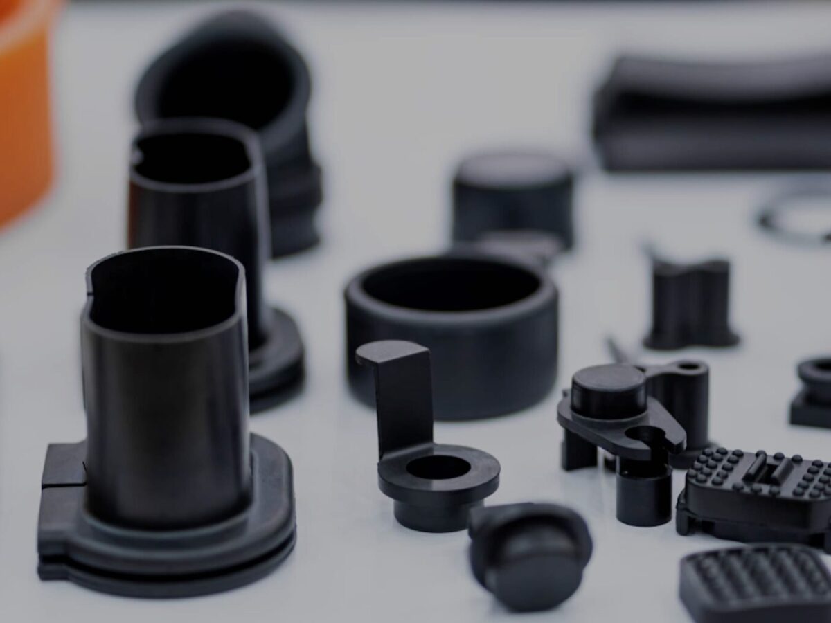
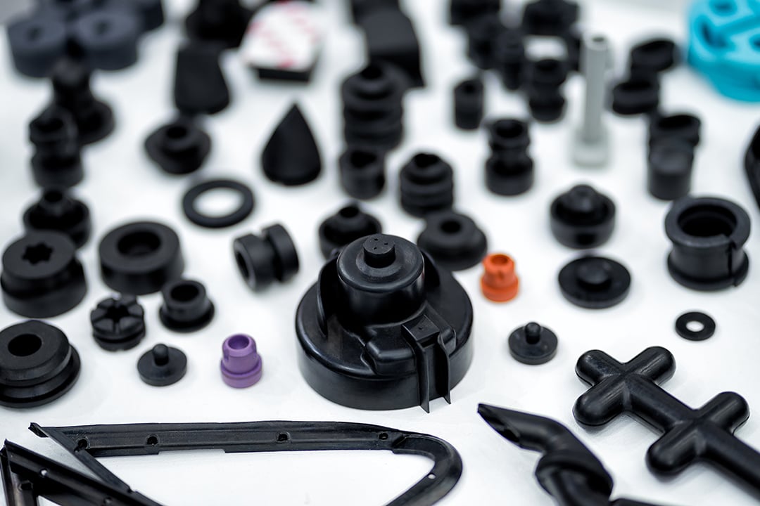
What are injection molded parts, and how are they manufactured?
Injection molded parts are components or products that are produced through the injection molding manufacturing process. Injection molding is a widely used manufacturing technique for creating plastic parts with high precision, complexity, and efficiency. Here’s a detailed explanation of injection molded parts and the process of manufacturing them:
Injection Molding Process:
The injection molding process involves the following steps:
1. Mold Design:
The first step in manufacturing injection molded parts is designing the mold. The mold is a custom-made tool that defines the shape and features of the final part. It is typically made from steel or aluminum and consists of two halves: the cavity and the core. The mold design takes into account factors such as part geometry, material selection, cooling requirements, and ejection mechanism.
2. Material Selection:
The next step is selecting the appropriate material for the injection molding process. Thermoplastic polymers are commonly used due to their ability to melt and solidify repeatedly without significant degradation. The material choice depends on the desired properties of the final part, such as strength, flexibility, transparency, or chemical resistance.
3. Melting and Injection:
In the injection molding machine, the selected thermoplastic material is melted and brought to a molten state. The molten material, called the melt, is then injected into the mold under high pressure. The injection is performed through a nozzle and a runner system that delivers the molten material to the mold cavity.
4. Cooling:
After the molten material is injected into the mold, it begins to cool and solidify. Cooling is a critical phase of the injection molding process as it determines the final part’s dimensional accuracy, strength, and other properties. The mold is designed with cooling channels or inserts to facilitate the efficient and uniform cooling of the part. Cooling time can vary depending on factors such as part thickness, material properties, and mold design.
5. Mold Opening and Ejection:
Once the injected material has sufficiently cooled and solidified, the mold opens, separating the two halves. Ejector pins or other mechanisms are used to push or release the part from the mold cavity. The ejection system must be carefully designed to avoid damaging the part during the ejection process.
6. Finishing:
After ejection, the injection molded part may undergo additional finishing processes, such as trimming excess material, removing sprues or runners, and applying surface treatments or textures. These processes help achieve the desired final appearance and functionality of the part.
Advantages of Injection Molded Parts:
Injection molded parts offer several advantages:
1. High Precision and Complexity:
Injection molding allows for the creation of parts with high precision and intricate details. The molds can produce complex shapes, fine features, and precise dimensions, enabling the manufacturing of parts with tight tolerances.
2. Cost-Effective Mass Production:
Injection molding is a highly efficient process suitable for large-scale production. Once the mold is created, the manufacturing process can be automated, resulting in fast and cost-effective production of identical parts. The high production volumes help reduce per-unit costs.
3. Material Versatility:
Injection molding supports a wide range of thermoplastic materials, allowing for versatility in material selection based on the desired characteristics of the final part. Different materials can be used to achieve specific properties such as strength, flexibility, heat resistance, or chemical resistance.
4. Strength and Durability:
Injection molded parts can exhibit excellent strength and durability. The molding process ensures that the material is uniformly distributed, resulting in consistent mechanical properties throughout the part. This makes injection molded parts suitable for various applications that require structural integrity and longevity.
5. Minimal Post-Processing:
Injection molded parts often require minimal post-processing. The high precision and quality achieved during the molding process reduce the need for extensive additional machining or finishing operations, saving time and costs.
6. Design Flexibility:
With injection molding, designers have significant flexibility in part design. The process can accommodate complex geometries, undercuts, thin walls, and other design features that may be challenging or costly with other manufacturing methods. This flexibility allows for innovation and optimization of part functionality.
In summary, injection molded parts are components or products manufactured through the injection molding process. This process involves designing amold, selecting the appropriate material, melting and injecting the material into the mold, cooling and solidifying the part, opening the mold and ejecting the part, and applying finishing processes as necessary. Injection molded parts offer advantages such as high precision, complexity, cost-effective mass production, material versatility, strength and durability, minimal post-processing, and design flexibility. These factors contribute to the widespread use of injection molding in various industries for producing high-quality plastic parts.


editor by CX 2023-11-27


