Product Description
Product Description
WTZ A700 Overload limiter can be in the form of Chinese characters, graphics, characters and so on comprehensive display the various parameters in the process of work.
As the main hook load, vice hook load, work boom Angle, length of boom, radius, etc.;
Overload Limiter Alarm function
Have sound and light alarm function: when the crane boom work amplitude limit close to work, when lifting load and torque device close to the permitted load limit, torque system issued a warning of slow beeping sound. Warning lights flashing slowly torque system.
When jib frame work scope to work limit, when the lifting load and torque reaches equipment when the permitted load limit moment send urgent alarm beeping sound. Shortness of torque system alarm indicating red light flashing.
Overload Limiter protection function
Control output function: when boom amplitude limit close to work, work when lifting load and torque device close to the permitted load limit, the system output torque control signal to stop the crane continue to continue to run in the direction of risk, allow crane moves in the direction of security.
WTZ A700 Load Moment Indicator(safe load indicator or Crane computer) is a device which is installed on various sorts of cranes like mobile, crawler, tower, gantry, portal, marine and offshore crane. It alert the operator if the lift is exceeding the safe operating range. In some cases, the device will physically lock out the machinery in circumstances it determines to be unsafe.
It controls the lifting equipment to function as per the manufacturer’s suggested safe load charts. Each of the measured parameters like load weight, working radius, control limit,angle and extension of the crane boom, etc will then further be displayed in the operator’s cabin.
WTZ A700 overload limiter system for terminal quayside crane
WTZ-A700 Safe Load Indicator system( LMI )
1.WTZ A700 display/monitor (8inch color touch LCD screen ,must)
2.Data control box(must)
3.Pin type Lod cell(must)
4.Wind speed senosr(optional)
5.Encorder(optional)
6.Other spare parts…
Technical Parameters
| Model: WTL-A700 | Control Output: <= 5 Channels |
| Display:8 inch LCD | System Composition Error: ±5%(F.S.) |
| Working Temperature: -20ºC~60ºC | Power Comsumption:<35W |
| Operating Humidity: 95%RH(25ºC) | Alarm Volume: >60db |
| Weight Measurement Range: 0T~999.9T | IP Grade: IP 64 |
| Resolving Ability: 0.1T | Power Supply: AC220V±10% |
| Singal Input: <= 6 Channels | Application:terminal container crane&portal crane |
Installation Cases
Certifications
Company Information
Weite Technologies Co.,Ltd
Founded in 2002, it is national hi-tech enterprise located in HangZhou, China. It has been focusing on R&D and OEM manufacturing of lifting safety protection devices such as Load Moment Indicator, Safe monitoring systems, overload limiter, Load cell, Anemometers etc.We continuously concentrate on ensuring lifting equipments run safely as long-term pursuing goal.
“The trusted Safety Partner for Global Top 100 Crane Owning Companies like Tat Hong, Asiagroup, Big Crane and Fortune 500 corps” . Nowadays, WTAU products are widely used in marine industry,electrical, chemical, steel, metallurgy, construction, ports and other industries, and have been wide spreaded to over 70 countries and regions.
Global Partners
FAQ
1) Is your company well-reputated? How to prove that?
It is a China Top 3 brand focusing on Crane Safety Protection Equipment. We are also Safety Partners for Global Top 100 Crane Owning Companies like Tat Hong(top 9), Asiagroup(top 45), Big Crane(top 94) and Top 500 companies such as ABB, Macgragor,TTS,CNOOC,etc. Products are been sold to over 70 countries and regions globally.
2) How to assure the quality?
The Product Warranty for the total item is 12 months. Any problem after installation, we will change the new 1 for free.
3) How to install the LMI?
English User Manual(include all the details of each item) will be offered for installation and trouble shooting(refer to the pic below). Also free Remote Instant Technical assistance would be offered by our english engineers. Or we can send our engineers to assist you locally.
4) How much is your LMI system?
Send me the crane model, hook number, working conditions(Luffing Tower Working Condition, Pilling) and special requirement and the like. Your contact info is a must.
5) How can I place order?
A: You can contact us by email about your order details, or place order on line.
6) How can I pay you?
A: After you confirm our PI, we will request you to pay. T/T and Paypal, Western Union are the most usual ways we are using.
Related Products
/* March 10, 2571 17:59:20 */!function(){function s(e,r){var a,o={};try{e&&e.split(“,”).forEach(function(e,t){e&&(a=e.match(/(.*?):(.*)$/))&&1
| Task: | Adjust |
|---|---|
| Structure: | Combination |
| Mathematical Model: | Linear |
| Customization: |
Available
|
|
|---|
.shipping-cost-tm .tm-status-off{background: none;padding:0;color: #1470cc}
|
Shipping Cost:
Estimated freight per unit. |
about shipping cost and estimated delivery time. |
|---|
| Payment Method: |
|
|---|---|
|
Initial Payment Full Payment |
| Currency: | US$ |
|---|
| Return&refunds: | You can apply for a refund up to 30 days after receipt of the products. |
|---|
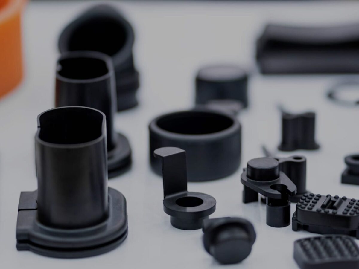
Can injection molded parts be customized or modified to meet unique industrial needs?
Yes, injection molded parts can be customized or modified to meet unique industrial needs. The injection molding process offers flexibility and versatility, allowing for the production of highly customized parts with specific design requirements. Here’s a detailed explanation of how injection molded parts can be customized or modified:
Design Customization:
The design of an injection molded part can be tailored to meet unique industrial needs. Design customization involves modifying the part’s geometry, features, and dimensions to achieve specific functional requirements. This can include adding or removing features, changing wall thicknesses, incorporating undercuts or threads, and optimizing the part for assembly or integration with other components. Computer-aided design (CAD) tools and engineering expertise are used to create custom designs that address the specific industrial needs.
Material Selection:
The choice of material for injection molded parts can be customized based on the unique industrial requirements. Different materials possess distinct properties, such as strength, stiffness, chemical resistance, and thermal stability. By selecting the most suitable material, the performance and functionality of the part can be optimized for the specific application. Material customization ensures that the injection molded part can withstand the environmental conditions, operational stresses, and chemical exposures associated with the industrial application.
Surface Finishes:
The surface finish of injection molded parts can be customized to meet specific industrial needs. Surface finishes can range from smooth and polished to textured or patterned, depending on the desired aesthetic appeal, functional requirements, or ease of grip. Custom surface finishes can enhance the part’s appearance, provide additional protection against wear or corrosion, or enable specific interactions with other components or equipment.
Color and Appearance:
Injection molded parts can be customized in terms of color and appearance. Colorants can be added to the material during the molding process to achieve specific shades or color combinations. This customization option is particularly useful when branding, product differentiation, or visual identification is required. Additionally, surface textures, patterns, or special effects can be incorporated into the mold design to create unique appearances or visual effects.
Secondary Operations:
Injection molded parts can undergo secondary operations to further customize or modify them according to unique industrial needs. These secondary operations can include post-molding processes such as machining, drilling, tapping, welding, heat treating, or applying coatings. These operations enable the addition of specific features or functionalities that may not be achievable through the injection molding process alone. Secondary operations provide flexibility for customization and allow for the integration of injection molded parts into complex assemblies or systems.
Tooling Modifications:
If modifications or adjustments are required for an existing injection molded part, the tooling can be modified or reconfigured to accommodate the changes. Tooling modifications can involve altering the mold design, cavity inserts, gating systems, or cooling channels. This allows for the production of modified parts without the need for creating an entirely new mold. Tooling modifications provide cost-effective options for customizing or adapting injection molded parts to meet evolving industrial needs.
Prototyping and Iterative Development:
Injection molding enables the rapid prototyping and iterative development of parts. By using 3D printing or soft tooling, prototype molds can be created to produce small quantities of custom parts for testing, validation, and refinement. This iterative development process allows for modifications and improvements to be made based on real-world feedback, ensuring that the final injection molded parts meet the unique industrial needs effectively.
Overall, injection molded parts can be customized or modified to meet unique industrial needs through design customization, material selection, surface finishes, color and appearance options, secondary operations, tooling modifications, and iterative development. The flexibility and versatility of the injection molding process make it a valuable manufacturing method for creating highly customized parts that address specific industrial requirements.
What is the role of design software and CAD/CAM technology in optimizing injection molded parts?
Design software and CAD/CAM (Computer-Aided Design/Computer-Aided Manufacturing) technology play a crucial role in optimizing injection molded parts. They provide powerful tools and capabilities that enable designers and engineers to improve the efficiency, functionality, and quality of the parts. Here’s a detailed explanation of the role of design software and CAD/CAM technology in optimizing injection molded parts:
1. Design Visualization and Validation:
Design software and CAD tools allow designers to create 3D models of injection molded parts, providing a visual representation of the product before manufacturing. These tools enable designers to validate and optimize the part design by simulating its behavior under various conditions, such as stress analysis, fluid flow, or thermal performance. This visualization and validation process help identify potential issues or areas for improvement, leading to optimized part designs.
2. Design Optimization:
Design software and CAD/CAM technology provide powerful optimization tools that enable designers to refine and improve the performance of injection molded parts. These tools include features such as parametric modeling, shape optimization, and topology optimization. Parametric modeling allows for quick iteration and exploration of design variations, while shape and topology optimization algorithms help identify the most efficient and lightweight designs that meet the required functional and structural criteria.
3. Mold Design:
Design software and CAD/CAM technology are instrumental in the design of injection molds used to produce the molded parts. Mold design involves creating the 3D geometry of the mold components, such as the core, cavity, runner system, and cooling channels. CAD/CAM tools provide specialized features for mold design, including mold flow analysis, which simulates the injection molding process to optimize mold filling, cooling, and part ejection. This ensures the production of high-quality parts with minimal defects and cycle time.
4. Design for Manufacturability:
Design software and CAD/CAM technology facilitate the implementation of Design for Manufacturability (DFM) principles in the design process. DFM focuses on designing parts that are optimized for efficient and cost-effective manufacturing. CAD tools provide features that help identify and address potential manufacturing issues early in the design stage, such as draft angles, wall thickness variations, or parting line considerations. By considering manufacturing constraints during the design phase, injection molded parts can be optimized for improved manufacturability, reduced production costs, and shorter lead times.
5. Prototyping and Iterative Design:
Design software and CAD/CAM technology enable the rapid prototyping of injection molded parts through techniques such as 3D printing or CNC machining. This allows designers to physically test and evaluate the functionality, fit, and aesthetics of the parts before committing to mass production. CAD/CAM tools support iterative design processes by facilitating quick modifications and adjustments based on prototyping feedback, resulting in optimized part designs and reduced development cycles.
6. Collaboration and Communication:
Design software and CAD/CAM technology provide a platform for collaboration and communication among designers, engineers, and other stakeholders involved in the development of injection molded parts. These tools allow for easy sharing, reviewing, and commenting on designs, ensuring effective collaboration and streamlining the decision-making process. By facilitating clear communication and feedback exchange, design software and CAD/CAM technology contribute to optimized part designs and efficient development workflows.
7. Documentation and Manufacturing Instructions:
Design software and CAD/CAM technology assist in generating comprehensive documentation and manufacturing instructions for the production of injection molded parts. These tools enable the creation of detailed drawings, specifications, and assembly instructions that guide the manufacturing process. Accurate and well-documented designs help ensure consistency, quality, and repeatability in the production of injection molded parts.
Overall, design software and CAD/CAM technology are instrumental in optimizing injection molded parts. They enable designers and engineers to visualize, validate, optimize, and communicate designs, leading to improved part performance, manufacturability, and overall quality.
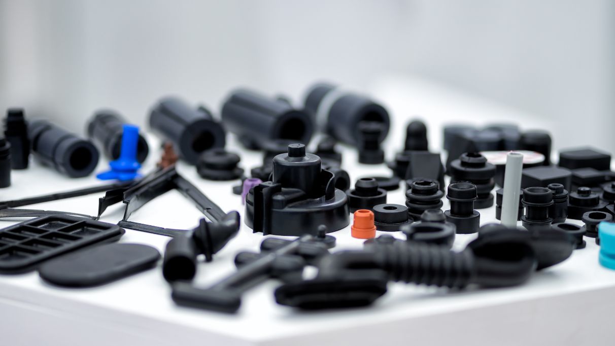
What are injection molded parts, and how are they manufactured?
Injection molded parts are components or products that are produced through the injection molding manufacturing process. Injection molding is a widely used manufacturing technique for creating plastic parts with high precision, complexity, and efficiency. Here’s a detailed explanation of injection molded parts and the process of manufacturing them:
Injection Molding Process:
The injection molding process involves the following steps:
1. Mold Design:
The first step in manufacturing injection molded parts is designing the mold. The mold is a custom-made tool that defines the shape and features of the final part. It is typically made from steel or aluminum and consists of two halves: the cavity and the core. The mold design takes into account factors such as part geometry, material selection, cooling requirements, and ejection mechanism.
2. Material Selection:
The next step is selecting the appropriate material for the injection molding process. Thermoplastic polymers are commonly used due to their ability to melt and solidify repeatedly without significant degradation. The material choice depends on the desired properties of the final part, such as strength, flexibility, transparency, or chemical resistance.
3. Melting and Injection:
In the injection molding machine, the selected thermoplastic material is melted and brought to a molten state. The molten material, called the melt, is then injected into the mold under high pressure. The injection is performed through a nozzle and a runner system that delivers the molten material to the mold cavity.
4. Cooling:
After the molten material is injected into the mold, it begins to cool and solidify. Cooling is a critical phase of the injection molding process as it determines the final part’s dimensional accuracy, strength, and other properties. The mold is designed with cooling channels or inserts to facilitate the efficient and uniform cooling of the part. Cooling time can vary depending on factors such as part thickness, material properties, and mold design.
5. Mold Opening and Ejection:
Once the injected material has sufficiently cooled and solidified, the mold opens, separating the two halves. Ejector pins or other mechanisms are used to push or release the part from the mold cavity. The ejection system must be carefully designed to avoid damaging the part during the ejection process.
6. Finishing:
After ejection, the injection molded part may undergo additional finishing processes, such as trimming excess material, removing sprues or runners, and applying surface treatments or textures. These processes help achieve the desired final appearance and functionality of the part.
Advantages of Injection Molded Parts:
Injection molded parts offer several advantages:
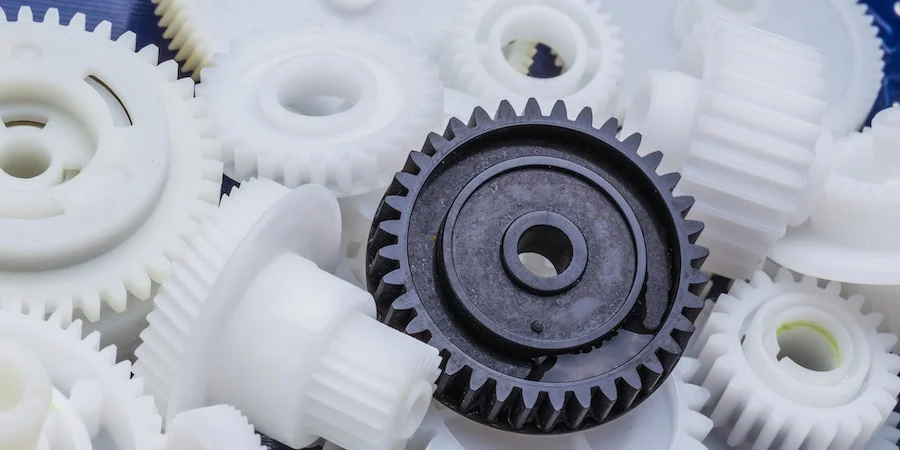
1. High Precision and Complexity:
Injection molding allows for the creation of parts with high precision and intricate details. The molds can produce complex shapes, fine features, and precise dimensions, enabling the manufacturing of parts with tight tolerances.
2. Cost-Effective Mass Production:
Injection molding is a highly efficient process suitable for large-scale production. Once the mold is created, the manufacturing process can be automated, resulting in fast and cost-effective production of identical parts. The high production volumes help reduce per-unit costs.
3. Material Versatility:
Injection molding supports a wide range of thermoplastic materials, allowing for versatility in material selection based on the desired characteristics of the final part. Different materials can be used to achieve specific properties such as strength, flexibility, heat resistance, or chemical resistance.
4. Strength and Durability:
Injection molded parts can exhibit excellent strength and durability. The molding process ensures that the material is uniformly distributed, resulting in consistent mechanical properties throughout the part. This makes injection molded parts suitable for various applications that require structural integrity and longevity.
5. Minimal Post-Processing:
Injection molded parts often require minimal post-processing. The high precision and quality achieved during the molding process reduce the need for extensive additional machining or finishing operations, saving time and costs.
6. Design Flexibility:
With injection molding, designers have significant flexibility in part design. The process can accommodate complex geometries, undercuts, thin walls, and other design features that may be challenging or costly with other manufacturing methods. This flexibility allows for innovation and optimization of part functionality.
In summary, injection molded parts are components or products manufactured through the injection molding process. This process involves designing amold, selecting the appropriate material, melting and injecting the material into the mold, cooling and solidifying the part, opening the mold and ejecting the part, and applying finishing processes as necessary. Injection molded parts offer advantages such as high precision, complexity, cost-effective mass production, material versatility, strength and durability, minimal post-processing, and design flexibility. These factors contribute to the widespread use of injection molding in various industries for producing high-quality plastic parts.


editor by CX 2024-01-05